
| Version 1 (modified by , 7 years ago) ( diff ) |
|---|
Serial Peripheral Interface Bus (SPI)
The Serial Peripheral Interface bus is a synchronous serial communication interface specification used for short distance communication primary in embedded systems. The interface was originally developed by Motorola and can be used in a master or slave configuration. It is typically used as a 3-wire bus containing the following signals (other than power and ground and chip-selects):
- SCLK
- MISO
- MOSI
- SS# (Optional Slave Select)
SPI can be a multi-slave bus if chip selects are used which are asserted by the host controller to enable one device at a time.
References:
USB Expansion devices
A SPI master can also be added via USB expansion. For example:
- GW16113 firmware-flexible USB 2.0 FS expansion
- Commell MPX-24794S USB 2.0 FS SPI/I2C/GPIO expansion
Ventana
GW5220
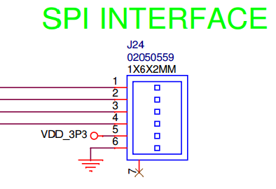
The i.MX6 Ventana GW5220 brings out the IMX6 ECSPI3 bus to the 6-pin J24 expansion connector for connection to a 3.3V TTL SPI slave device:
- J24.1 - MOSI
- J24.2 - MISO
- J24.3 - SCLK
- J24.4 - SS0#
- J24.5 - 3.3V
- J24.6 - GND
GW54xx (Revision E+)
The i.MX6 Ventana GW54xx brings out the IMX6 ECSPI2 bus to the 6-pin J32 expansion connector for connection to a 3.3V TTL SPI slave device:
- J32.1 - MOSI
- J32.2 - MISO
- J32.3 - SCLK
- J32.4 - SS0#
- J32.5 - 3.3V
- J32.6 - GND
Adding Kernel Support for Specific SPI Devices
In order to support the specific device you plan to connect an addition to the GW5220 device tree must be made.
- Follow these instructions up to and including step 5 of "Building the Linux Kernel"
- Open the file at
.../linux-imx6/arch/arm/boot/dts/imx6qdl-gw52xx.dtsiand find the node labeled "&ecspi3" (if absent, jump to the above section before continuing) - In the same location as the comment in step 5 of the above section, add your appropriate device configuration in a node beginning with "flash: "
- Continue the instructions from step 1 to finish building your new kernel
An example of a properly made configuration node for a m25p32-vme6g nor flash device would be:
flash: m25p80@0 {                         /* "m25p80@0" parameter is the driver responsible for controlling your device */
        compatible = "m25p32";            /* "m25p32" parameter is your device ID string */
        spi-max-frequency = <30000000>;   /* assigned value is your device frequency specified by its datasheet (in decimal) */
        reg = <0>;                        /* is generally 0 for single device connections */
        #device-width = <1>;              /* These next three lines are not comments, but rather specially formatted
        #address-cells = <1>;              * attributes that the driver will receive. The actual values assigned here
        #size-cells = <1>;                 * are device specific, and should be entered after consulting the data sheet
                                           */
        partition@0 {                     /* The label of the 0th partition; following partitions follow the "partition@X" format */
                label = "data";           /* The name of this partition  */
                reg = <0x0 0x2000000>;    /* The starting address, followed by the length of the partition (in hex) */
        };
};
Note that the values shown in the above node are specific to the m25p32-vme6g, and can vary greatly from the actual device you are using. Replace attribute values as necessary.
When searching for your device ID string or its controlling driver, searching via a LXR site like the one at missing link electronics for your device name can be helpful.
Laguna
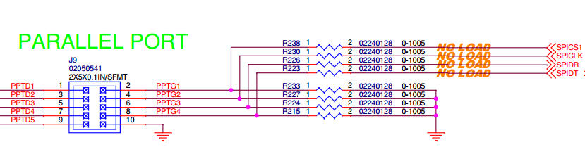
While SPI is used for on-board FLASH storage for many Laguna boards, it also is brought out to the J9 expansion connector available on the Laguna GW2388:
- J9.2 - CS#
- J9.4 - SCLK
- J9.6 - MISO
- J9.8 - MOSI
- J9.10 - GND

Attachments (2)
- GW5220-SPI-INTERFACE.png (13.4 KB ) - added by 7 years ago.
- spi2388.png (32.8 KB ) - added by 7 years ago.
Download all attachments as: .zip