
| Version 3 (modified by , 6 years ago) ( diff ) |
|---|
Controller Area Network (CAN) Bus
Most boards in the Gateworks Ventana product family has one or more CAN bus interfaces. The CAN bus is popular in automotive, industrial, and marine applications where robust signaling is necessary in an electrically noisy environment.
CAN bus is one of the five protocols used in the on-board diagnostics (OBD)-II vehicle diagnostics standard mandatory for all cards and light trucks sold in the US since 1996.
CAN bus was originated in 1983 at Bosch and was released in 1986 at the Society of Automotive Engineers (SAE). The first CAN controller chips were produced by Intel and Philips and came to market in 1987. The CAN 2.0 spec was published in 1991.
Signalling and Termination
CAN is a form of multidrop serial communications using a differential signal making it suitable for noisy environments. As it is differential the bus is made of up two wires:
- CAN_H
- CAN_L
The voltage drop from CAN_H to CAN_L determines a 0 or a 1 bit.
Typically a CAN bus network requires a single 120ohm termination resistor at each end of the bus (these are in parallel so a properly terminated bus should have a total resistance of 60 ohms). The maximum distance for any device from the bus is six meters.
Arbitration
CAN bus arbitration happens when two or more ECUs (nodes) start to transmit at the same time. Every transmitter listens to the bus to ensure what it sent was what it received - if there is a difference than the CAN controller stops transmitting. The winner will always be the CAN messages with the lowest identifier.
Framing
There are four different types of frames for communicating info and the state of the bus:
- Data frame (send data) - uses a header (identifier) of 29bits (CAN 2.0B) or 11bits (CAN 2.0A) followed by data (0 to 8 bytes in length)
- Request frame (request data)
- Error frame (indicates an error)
- Overload frame (inserts a delay)
CAN FD spec
The CAN FD spec was published in 2012 and specified an improved CAN data link layer protocol which extends the data section of the message from 8 bytes to 64 bytes per frame (not all devices support this).
Specifications and standards
- ISO 11898-1 or ISOBUS (2003) describes the CAN data link layer protocol
- SAE J1939 is a standard maintained by Society of Automotive Engineers (SAE) defining how information is transferred across a network to allow ECUs to communication information (a software specification that rides on top of a CAN bus). It uses CAN 2.0B and replaces J1587 and J1708. It is used on commercial vehicles (tractor/trailers, cement mixers, military trucks, etc). Paramter Group Number (PGN) indicates the message being sent.
- NMEA 2000 (aka NMEA2k or N2K) is compatible with CAN Bus and is used for connecting marine sensors and display units within ships and boards. It uses SAE J1939, runs at 250kbps and specifies a standardised DeviceNet Micro-C M12 5-pin screw connector. Raymarine, SeaTalk 2, Raymarine SeaTalk, Simrad Simnet, Furuno CAN are rebranded imlementations of NMEA 2000 though may not use the standardized connectors.
SAE J1939
While not currently part of the Gateworks BSP's, there are various sources for a source-code level software stack for SAE J1939:
- Simma Software - available for purchase / license
- ESD Electronic system design - available for purchase / license
CAN ID
Devices on a CAN bus have a unique CAN ID which also defines the message priority. In the early 1990's the choice of IDs was done simply on the basis of identifying the type of data and the sending node but this has now changes where IDs are determined based on the deadline of the message (lower the number, higher the priority).
Gateworks Hardware
Gateworks uses the MCP2562 Transceiver chip from Microchip.
- Note: There is an EEPROM bit that must be set for CAN to be enabled. This is already done by default on most boards. Please contact Gateworks support for any further questions.
Boards that feature CAN Bus:
- GW52xx
- GW53xx
- GW54xx
- GW551x (*No Transceiver on GW5510, use with GW16111)
To find which pins and which connectors have the CAN Bus signals, please refer to the hardware user manuals
Boards that do not have CAN Bus:
- GW552x
- GW51xx
- GW553x
- GW2xxx
CAN Bus can be found on the GW16113 Expansion card, but note this card will need to be custom programmed and does not have a transceiver.
CAN Transceiver STBY
The STBY signal is connected to a GPIO on Ventana baseboards:
- GW54xx/GW53xx: gpio-2
- GW52xx: gpio-9
- When using a 'device-tree' kernel such as the 3.10.x and beyond kernel under OpenWrt, you must manually enable the transceiver:
- For example on a GW53xx/GW54xx:
echo 2 > /sys/class/gpio/export
echo out > /sys/class/gpio/gpio2/direction
echo 0 > /sys/class/gpio/gpio2/value
- For example on a GW52xx:
echo 9 > /sys/class/gpio/export
echo out > /sys/class/gpio/gpio9/direction
echo 0 > /sys/class/gpio/gpio9/value
- This is done automatically when the transceiver interface is brought up in the 3.0.35 kernel used on Yocto v1.3 and Android BSP's
- For example on a GW53xx/GW54xx:
Software
CAN bus is supported under Yocto, OpenWrt, and Android Board Support Packages for the Ventana product family.
Software included in Gateworks BSP:
- kernel driver: flexcan (a SocketCAN driver)
- userspace:
- can-utils (gitorious) - a set of the major community tools that are usually used and references (does not require libsocketcan to compile or run)
Other Software:
- canutils (PTX) - five tools that are used and referenced in 'PTX dist' board support packages. These tools are not very featureful and no longer maintained. The 'canconfig' tool is used to configure the CAN interface as an alternative to the 'ip' tool and uses libsocketcan
- libsocketcan - a library for people that want to configure and control CAN interfaces from C code (instead of using the 'ip' tool from the iproute2 package
IMX6 Kernel drivers - SocketCAN
SocketCAN is a set of open source CAN drivers and a networking stack contributed by Volkswagon Research to the Linux kernel and was formerly known as Low Level CAN Framework (LLCF).
The Freescale IMX6 FlexCAN module is a full implementation of the CAN protocol specification version 2.0 B which supports both standard and extended message frames. The flexcan driver source can be found at:
General Notes:
- canbus is broadcast-only
- no MAC-layer addressing like ethernet - the CAN-identifier (can_id) is used for arbitration on the CAN-bus therefore must be chosen uniquely on the bus.
- the CAN-identifier (can_id) determines the priority of the messages on the bus
- there are two CAN protocols to choose from: CAN_RAW, and CAN_BCM (broadcast manager)
- the basic CAN frame is:
struct can_frame { canid_t can_id; /* 32bit CAN_ID + EFF/RTF/ERR flags */ __u8 can_dlc; /* frame payload length in bytes (0..8) */ __u8 data[8] __attribute__((aligned(8)))); /* aligned on 64bit boundary so payload can be used with own structs */ }; - CAN FD (flexible data rate) support: for new CAN FD capable CAN controllers that support two different bitrates for the arbitration phase and the payload phase of the CAN FD frame and up to 64 bytes of payload.
Reference:
- source: https://gitorious.org/linux-can
- http://en.wikipedia.org/wiki/SocketCAN - includes userspace configuration examples and code examples using sockets
- https://www.kernel.org/doc/Documentation/networking/can.txt - detailed socket API
can-utils
The can-utils package is a sub-project of the SocketCAN project and is the more popular and maintained set of userspace configuration tools for SocketCAN interfaces.
This is the package that exists on the latest Gateworks OpenWrt and Yocto v1.6 BSP's.
Configure SocketCAN interface (using ip from the iproute2 package) (for 250kbps in this example):
ip link set can0 type can bitrate 250000 listen-only off
ip link set can0 up
Send a frame (consisting of 4 hex bytes to 0x100):
cansend can0 100#11.22.33.44
Receive frames:
candump can0
Example:
root@ventana:~# candump can0
  can0  1CFF0105   [7]  47 9F 10 00 00 00 00
  can0  1CFF0105   [7]  47 9F 00 FF FF 00 00
  can0  1CFF0105   [5]  47 9F 20 00 00
  can0  1CFF0105   [7]  47 9F 10 00 00 00 00
  can0  1CFF0105   [7]  47 9F 00 FF FF 00 00
  can0  1CFF0105   [5]  47 9F 20 00 00
  can0  1CFF0105   [7]  47 9F 10 00 00 00 00
  can0  1CFF0105   [7]  47 9F 00 FF FF 00 00
  can0  1CFF0105   [5]  47 9F 20 00 00
  can0  1CFF0105   [7]  47 9F 10 00 00 00 00
  can0  1CFF0105   [7]  47 9F 00 FF FF 00 00
  can0  1CFF0105   [5]  47 9F 20 00 00
  can0  1CFF0105   [7]  47 9F 10 00 00 00 00
  can0  1CFF0105   [7]  47 9F 00 FF FF 00 00
Notes:
- see #TransceiverSTBY above to enable the SocketCAN transceiver
Reference:
PTX canutils and libsocketcan
The PTX flavor of canutils (http://git.pengutronix.de/?p=tools/canutils.git) provides five tools that are commonly found referenced online which contains the 'canconfig' utility (which uses libsocketcan) to configure the CAN interface as an alternative to the 'ip' tool.
Freescale still uses canutils and the canconfig utility thus you will find it in some of the IMX online documentation. Gateworks moved to the more popular full-featured and maintained can-utils configuration utilities for its OpenWrt BSP and its Yocto v1.6 BSP. If you are using an older version of OpenWrt or Yocto BSP and have the 'canconfig' utility you can use these configuration instructions.
Configure the following on a Ventana board:
canconfig can0 bitrate 125000
ifconfig can0 up
To send from the Ventana board command prompt type:
cansend can0 -i0x100 0x11 0x22 0x33 0x44
To recieve (on another Ventana board, or from CanAnalyzer USB Device) type the command:
canecho can0 -v
Notes:
- see #TransceiverSTBY above to enable the SocketCAN transceiver
References:
Android BSP
- Freescale has not released can-utils or userspace utilities for CAN in Android
- Android requires standard socket programming to access the CAN0 socket interface.
- To check for can0 in Android, use the command:
root@ventana:/ # busybox ifconfig -a
can0      Link encap:UNSPEC  HWaddr 00-00-00-00-00-00-00-00-00-00-00-00-00-00-00-00
          NOARP  MTU:16  Metric:1
          RX packets:0 errors:0 dropped:0 overruns:0 frame:0
          TX packets:0 errors:0 dropped:0 overruns:0 carrier:0
          collisions:0 txqueuelen:10
          RX bytes:0 (0.0 B)  TX bytes:0 (0.0 B)
          Interrupt:142
More notes in this thread here: https://community.freescale.com/thread/307066
CAN Bus Hardware
NMEA 2000 Equipment
Some examples of NMEA 2000 equipment we have tested our products with:
- Lowrance NMEA 2000 Network Starter Kit - Includes 2 terminatoring resistors, 1 2ft extension cable, 1 15ft extension cable, 2 T-connectors, and a power node connector
- Lowrance POINT-1 GPS - NMEA 2000 GPS (12V powered 250kbps bitrate)
Chip-Level
An example chip that would interface to the Ventana board would be:
- A CAN controller chip would be something like Microchip MCP2515
CAN Bus Development Tools
- Microchip APGDT002 Can Bus Analyzer:
- This product allows us to try CAN from a computer with a USB port. This is for 'testing and development'
- Digikey APGDT002
- Manual
- Software:
- Windows software can be found on the product page.
- NOTE: When installing on Windows7+ be sure to run the installer as Administrator or you will run into errors
- Open the software and drop down the 'Tools' menu item to start a rolling trace or to transmit.
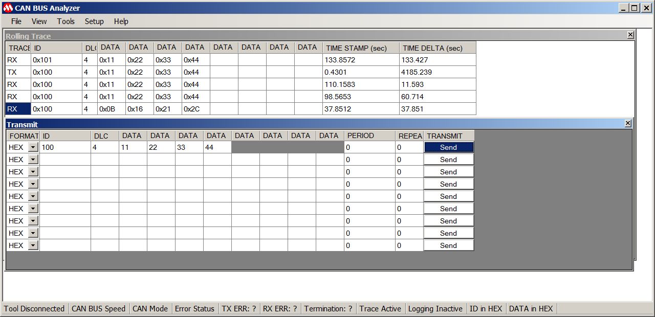
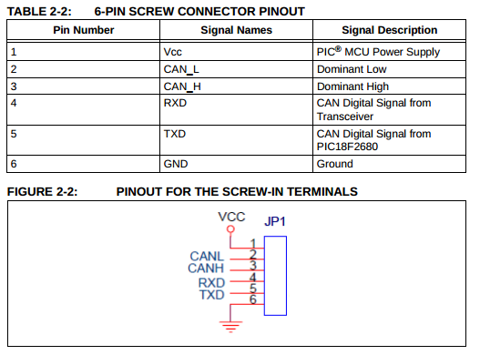
- Connection (look at silkscreen): D+ GND D- (Looking at top of board from edge) (see manual for Can Bus Analyzer tool if used)


References
- CAN Bus Wikipedia: http://en.wikipedia.org/wiki/CAN_bus
- SocketCAN API: https://www.kernel.org/doc/Documentation/networking/can.txt
- CAN tutorial
- SAE J1939 Presentation
Attachments (2)
- cananalyzer.jpg (111.8 KB ) - added by 6 years ago.
- canpins.png (32.9 KB ) - added by 6 years ago.
Download all attachments as: .zip