
| Version 15 (modified by , 3 years ago) ( diff ) |
|---|
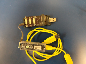
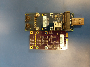
GW16113 miniPCIe Expansion Module
The GW16113 is a Mini-PCIe GPIO expansion module that offers more GPIO to a Gateworks SBC.
Disclaimer : This card has only been tested on Gateworks Single Board Computers. Gateworks only provides support when used on a Gateworks SBC.
- GW16113 Product Page
- Software Manual - This wiki page acts as the software manual.
Features
Specifications:
- MiniPCIe form-factor
- MiniPCIe socket providing PCIe signalling and USB signalling pass-through
- Uses Mini-PCIe USB pins Pin 36 USB- and Pin 38 USB+
- 3x 10pin Port connectors:
- 1x 3.3V power pin
- 1x ground
- 8x I/O (24 total) 3.3V TTL with various termination configurations
- USB FS interface to host processor
- On-board USB hub (to provide USB pass-through to miniPCIe socket)
- 2x surface mount green user-controllable LED's
Gateworks will offer the GW16113 pre-programmed with all pins configured as GPIO / DIO.
I/O pins
The 24 I/O terminals available on the GW16113 are 3.3V TTL level
Pin I/O details:
- Voltage
| Parameter | Description | Min | Max | Comment |
|---|---|---|---|---|
| VGPIO | Range of Input Voltage | -0.5V | 3.8V | VSSD-0.5 to VDDD+0.5 |
| VMIN | Maximum Input voltage | 3.8V | VDDD+0.5 | |
| VIH | Input voltage high threshold | 2.31V | - | 0.7 x VDDIO |
| VIL | Input voltage low threshold | - | 0.99V | 0.3 x VDDIO |
| VOH | Output voltage high | 2.9V | - | VDDIO-0.4 |
| VOL | Output voltage low | - | 0.8V | IOL = 25mA |
- See CY8C58LP datasheet section 11.4 for more details
- Current capabilities
| Parameter | Description | Source | Sink | Notes |
|---|---|---|---|---|
| IGPIO | J2/P3,J1/P0 current | 4 mA | 8 mA | |
| ISIO | J1/P12 current | 4 mA | 25 mA | 1 |
- See CY8C58LP datasheet Figure 11-8 and 11-9 for GPIO (J2/P3 and J1/P0) output curves
- See CY8C58LP datasheet Figure 11-10 and 11-11 for SIO (J1/P12) output curves
- The GW16113 has 332 ohm series termination resistors between the PSoC pins and the external connectors limiting the current to 10mA - contact sales@… for information on creating a Gateworks special with modified termination
Cable and Connector Information
Cables are sold separately.
General Purpose IO (GPIO)
The I/O pins allows a variety of Drive Modes:
- strong drive
- open drain, drives high
- open drain, drives low
- resistive pull-up (5.6kOhm typ)
- resistive pull-down (5.6kOhm typ)
- resistive pull up/down (5.6kOhm typ)
- high impedance digital
- high impedance analog
The USB API will allow the following:
- get/set I/O direction (input/output)
- get/set digital logic level
- set digital logic level
- configure power-up pin drive mode
Reference:
On Board LEDs
There are two on-board LED's that can be turned on or off.
The USB API will allow the following:
- enable/disable LED
Software Support
There are two pieces of software dealing with the GW16113:
- The GW16113 firmware that is flashed onto the PSoc chip (pre-installed from factory)
- The userspace program that controls the GPIOs, etc
Linux Userspace Utilities
gwsoc
Gateworks will provide a gwsoc command-line utility which will make use of the popular open-source and cross-platform HIDAPI and libusb libraries for:
- updating firmware (the firmware dictates the feature matrix for the I/O pins)
- accessing the various features (ie configuring GPIO's etc).
The gwsoc application will come pre-installed on the various Gateworks Board Support Package (BSP) firmware images. Source-code is also provided (see building gwsoc)
The gwsoc application currently is what is used to get/set GPIO configuration using 32bit registers mapped as follows on the GW16113:
| bit | PSoC Port / Pin | GW16113 |
|---|---|---|
| 0 | P12.0 (SIO) | J1.1 |
| 1 | P12.1 (SIO) | J1.2 |
| 2 | P12.2 (SIO) | J1.3 |
| 3 | P12.3 (SIO) | J1.4 |
| 4 | P12.4 (SIO) | J1.5 |
| 5 | P12.5 (SIO) | J1.6 |
| 6 | P12.6 (SIO) | J1.7 |
| 7 | P12.7 (SIO) | J1.8 |
| 8 | P3.0 (GPIO) | J2.1 |
| 9 | P3.1 (GPIO) | J2.2 |
| 10 | P3.2 (GPIO) | J2.3 |
| 11 | P3.3 (GPIO) | J2.4 |
| 12 | P3.4 (GPIO) | J2.5 |
| 13 | P3.5 (GPIO) | J2.6 |
| 14 | P3.6 (GPIO) | J2.7 |
| 15 | P3.7 (GPIO) | J2.8 |
| 16 | P0.0 (GPIO) | J3.1 |
| 17 | P0.1 (GPIO) | J3.2 |
| 18 | P0.2 (GPIO) | J3.3 |
| 19 | P0.3 (GPIO) | J3.4 |
| 20 | P0.4 (GPIO) | J3.5 |
| 21 | P0.5 (GPIO) | J3.6 |
| 22 | P0.6 (GPIO) | J3.7 |
| 23 | P0.7 (GPIO) | J3.8 |
| 24 | unused | |
| 25 | unused | |
| 26 | unused | |
| 27 | unused | |
| 28 | unused | |
| 29 | unused | |
| 30 | P2.0 (GPIO) | D7 LED |
| 31 | P2.1 (GPIO) | D8 LED |
Example usage:
- show usage:
# gwsoc
GWSoC Utility v1.00
usage: gwsoc  [-p filename] [gpio[=val]] [gpiodir[=val]] [config<n>[=<val>]]
- program GW16113_HID-GPIO firmware:
# gwsoc -p GW16113_HID-GPIO.cyacd
- get gpio direction register:
# gwsoc gpiodir
GWSoC Utility v1.00
GWSoC_HID: 0x2beb:0x1110 Gateworks Corporation GW16113_HID_GPIO 660070
gpiodir=0x00ffffff
- the value of 0x00ffffff (bit0-23 set) indicate that all I/O's are configured for input
- set gpio direction register (set bit for input, clear for output):
# gwsoc gpiodir=0x00ff00ff
GWSoC Utility v1.00
GWSoC_HID: 0x2beb:0x1110 Gateworks Corporation GW16113_HID_GPIO 660070
gpiodir=0x00ff00ff
- the value of 0x00ff00ff (bit0-7,16-23 set) configures P12 (J1) and P0 (J3) as inputs and P3 (J2) as outputs
- set gpio data register (set bit to drive high, clear to drive low)
# gwsoc gpio=0x00005500
GWSoC Utility v1.00
GWSoC_HID: 0x2beb:0x1110 Gateworks Corporation GW16113_HID_GPIO 660070
gpio=0x00005500
- the value of 0x00005500 indicates to drive P3.0,2,4,6 cooresponding to J2.1,3,5,7 logic high
- get gpio data register:
# gwsoc gpio
GWSoC Utility v1.00
GWSoC_HID: 0x2beb:0x1110 Gateworks Corporation GW16113_HID_GPIO 660070
gpio=0x00005500
- the value of 0x00005555 indicates that P12.0,2,4,6 cooresponding to J1.1,3,5,7 are reading high (these are inputs per the gpiodir setting above) and P3.0,2,4,6 cooresponding to J2.1,3,5,7 are outputing logic high
LED control:
- Set correct direction and turns D7 and D8 on
gwsoc gpiodir=0x000000000
gwsoc gpio=0x000000000
- Turns off
gwsoc gpio=0xc0000000
- Illuminate only D8
gwsoc gpio=0x80000000
- Illuminate only D7
gwsoc gpio=0x80000000
Building gwsoc from source
To build the gwsoc application on an Ubuntu Linux host:
git clone http://github.com/Gateworks/gwsoc
cd gwsoc/gwsoc
sudo apt-get install build-essential libudev-dev libusb-1.0-0-dev libhidapi-dev # install dependencies
make
You may also want to install a udev rule to allow group ownership of hid devices for the plugdev group:
# cat /etc/udev/rules.d/99-hid.rules
KERNEL=="hidraw*", SUBSYSTEM=="hidraw", MODE="0664", GROUP="plugdev"
PSoc 5LP and Firmware
The GW16113 is based upon the Cypress PSoC 5LP device.
References:
- PSoC 5LP Product page
- PSoC5LP CY8C58LP Family Datasheet
- PSoC5LP Component list
- PSoC5LP Architecture Technical Reference Manual (TRM)
Programming PSoc Firmware
- Compile the firmware using the PSoc creator detailed above
- Copy the file to the Gateworks SBC board that has the GW16113 installed
- Verify the gwsoc software is accessible via the command line on the Gateworks SBC
- Verify the USB code is still present in the new firmware image as this code is used to access and update the PSoc and without it, the board could be bricked.
- Program the firmware to the GW16113 with the program flag in the gwsoc application
gwsoc -p {filename}
Firmware
Pre-built firmware configurations may be available for download here.
Note The GW16113 is pre-programmed with all pins set to act as a GPIO / DIO.
The GW16113 uses the CY8C58LP (part number: CY8C5888LTI-LP097) from the PSoC5LP family which has the following:
- 32bit ARM Cortex-M3 CPU with 32 interrupts
- 24-channel DMA controller
- 24-bit 64-tap fixed-point digital filter processor (DFB)
- 256KB program flash
- 64KB RAM
- 2KB EEPROM
- Cypress CapSense support
- 1.024V +/- 0.1% internal voltage reference
References:
Firmware Images
The current firmware images available from Gateworks here are:
- GW16113_HID_GPIO - Vendor-ID/Product-ID: 0x2beb:0x1110 (all pins set to act as a GPIO / DIO)
The firmware resides in the 256KB PSoC FLASH therefore is non-volatile and contains both the bootloader as well as the main application. See below regarding firmware updates.
Firmware Updates
The PSoC has 256KB of programmable non-volatile FLASH that are used to contain the 'firmware application'. The pre-built firmware images provided by Gateworks contain a PSoC5 Bootloader application that allows for USB updates of the main application (aka bootloadable) firmware.
GW16113 bootloader details:
- Bootloader is programmed at the factory via JTAG and is not able to be updated via USB (technically an application firmware can be created that allows updating the bootloader however Gateworks does not currently support this)
- USB Vendor-ID and Product-ID of bootloader: 0x2beb:0x1100
- Bootloader application is run when GW16113 comes out of reset (when PCI_RESET# is released) and will do one of the following depending on EEPROM configuration:
- remain in the bootloader awaiting a command (to jump to existing app, or program new app)
- remain in the bootloader awaiting a command if the state of the I/O ports latched coming out of reset matches a predefined value, otherwise jump to the application immediately
- jump directly to application
- main application can be instructed to jump to the bootloader and wait for a command (to allow firmware updating)
Options 1 and 2 above are designed to provide a fool-proof way of recovering from a failed firmware update, or faulty firmware that does not allow a method to jump back to the bootloader.
The factory default configuration is to stay in the bootloader a logic value of 0x55 (pin1,3,5,7 logic high, pin2,4,6,8 logic low) is latched on P12 (J1) when the GW16113 comes out of reset (option 2 above).
The bootloader configuration is stored in the PSoC EEPROM and can be altered via the gwsoc application (or directly by the main application if using custom firmware) if the default configuration does not suit your needs.
The gwsoc application running on the host processor has the ability to instruct the application to jump to the bootloader and await a command for updating the main application firmware. The '-p' command-line option is used to update the firmware providing a '.cyacd' file.
Examples:
- program GW16113_HID-GPIO firmware:
wget http://dev.gateworks.com/gwsoc/gw16113/GW16113_HID-GPIO.cyacd
gwsoc -p GW16113_HID-GPIO.cyacd
If for some reason the use case demands the 15KB FLASH space (of 256KB available) used by the bootloader or the ability to update the firmware via USB is not desired, the firmware can be customized by the user to eliminate the bootloader. The resulting firmware would need to be programmed via JTAG. Contact sales@… if this is a requirement.
Attachments (2)
-
cypress16115.jpg
(44.8 KB
) - added by 8 years ago.
cypressand16115
-
1611516113.jpg
(44.2 KB
) - added by 8 years ago.
16115and16113
Download all attachments as: .zip