
| Version 46 (modified by , 5 years ago) ( diff ) |
|---|
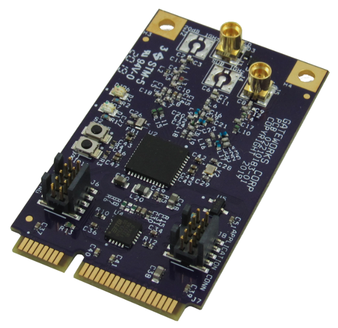
- GW16122 - Mini-PCIe Radio for Internet of Things - IoT
- GW16122 Development
- CC1350STK Notes
GW16122 - Mini-PCIe Radio for Internet of Things - IoT
Software Disclaimer: This hardware was designed from a Texas Instruments Reference design. Thus, all software support is community supported through Texas Instruments.
Welcome

This wiki page is about the Gateworks GW16122 IoT Radio Card that is based off the TI CC1350 Reference design.
This enables Gateworks SBCs to act as a collector or gateway to other IoT sensors over the Sub-1GHz Radio band. This band allows for long range and low power communication without any carrier subscription required. No consortium or software subscriptions are required. TI has made all software open source and available.
Advantages of Gateworks IoT solution over SigFox, LoRa, Zigbee, etc:
- Long Range
- Create your own network
- Do not rely on coverage of pre-existing networks (Verizon, AT&T, etc)
- Open Source provided software by TI
- No extra fees, subscription, etc
- No joining of alliances/consortiums/etc
- Works in remote areas where no coverage from other networks/carriers exist

Getting Started
It is beneficial to read this entire wiki page before getting started to gain knowledge about the product. Note that a majority of information required for an advanced IoT solution will come from TI.
Please follow the below steps to get started with the Gateworks hardware:
Hardware Requirements
All items purchased seperately
- Gateworks Ventana or Newport Single Board Computer
- Gateworks GW16122 IoT Card
- Gateworks GW10124 900Mhz Antenna
- Gateworks GW10074 MMCX to SMA Female Adapter Cable
- Ti CC1350 LaunchPad
- Gateworks SBC and GW16122 are the 'collector' in the system. This CC1350 LaunchPad becomes the 'sensor' for development.
- USB to Mini-PCIe Adapter
- This allows the Gateworks GW16122 to be connected to a Laptop / PC for programming purposes.
- Option #1 - Amazon - Requires rubberband to hold GW16122 in
- Option #1 - DHGate - May require USB extension cable
Software Requirements
Most software must be acquired from Ti because it is held behind a EULA.
You will need to download 2 software packages from TI on a Linux PC:
- TI SimpleLink SDK SIMPLELINK-CC13X0-SDK
- TI 15.4 Stack TI-15-4-STACK-GATEWAY-LINUX-SDK
There are 3 or more pieces of software:
- GW16122 firmware: pre-installed (so you can skip this step) is called the CoProcessor firmware
- Download the SDK here: SIMPLELINK-CC13X0-SDK
- Gateworks tested with SDK version 1.40.xx
- There is a precompiled binary in the SDK here:
- /usr/src/ti/simplelink_cc13x0_sdk_xxx/examples/rtos/CC1350_LAUNCHXL/ti154stack/hexfiles/coprocessor_cc13x0_lp.hex
- Built from the source code here:
- /usr/src/ti/simplelink_cc13x0_sdk_xxx/examples/rtos/CC1350_LAUNCHXL/ti154stack/coprocessor
- Download the SDK here: SIMPLELINK-CC13X0-SDK
- CC1350 LaunchPad Sensor Node Firmware
- There is a precompiled binary .hex file in the SIMPLELINK-CC13X0-SDK from step 1:
- /usr/src/ti/simplelink_cc13x0_sdk_xxx/examples/rtos/CC1350_LAUNCHXL/ti154stack/hexfiles/default/sensor_default.hex
- Gateworks tested with SDK version 1.40.xx
- Install firmware to Sensor LaunchPad with this information
- Additional TI Links here:
- /usr/src/ti/simplelink_cc13x0_sdk_xxx/examples/rtos/CC1350_LAUNCHXL/ti154stack/hexfiles/default/sensor_default.hex
- There is a precompiled binary .hex file in the SIMPLELINK-CC13X0-SDK from step 1:
- Install Ubuntu 14.04 trusty-ventana (~210MB) on Gateworks SBC
- Note Ubuntu Xenial 16.04 is not supported at this time
- The collector application running in Ubuntu on the Gateworks SBC
- Must download Ti-15-4 Stack from Ti onto Linux Desktop http://www.ti.com/tool/download/TI-15-4-STACK-GATEWAY-LINUX-SDK
- Once installed on desktop, find the file: ti154stack_linux_x64_2_04_00_19/prebuilt/bbb_prebuilt.tar.gz
- Copy this file (bbb_prebuilt.tar.gz) onto the Gateworks SBC running Ubuntu either through wget or USB drive or scp or other options.
- Extract this with the command on the Gateworks SBC:
tar xvf bbb_prebuilt.tar.gz
- Keep note of where this was extracted for future reference.
- Install the required packages for this application:
apt-get update
apt-get install -y build-essential nodejs
Getting Started Steps
- Program CC1350 LaunchPad Sensor node as described in software section above
- Connect GW16122 to Gateworks SBC in Mini-PCIe slot that supports USB
- Connect antenna to GW16122
- Gateworks SBC should have Ubuntu 14.04 Trusty installed as required in the software section above
- Connect ethernet cable to Gateworks SBC on the same network as a PC/Laptop (for web gui viewing from PC)
- Install the collector application software on the Gateworks SBC as described above in the software requirements section
Running the Collector Application
- To start the collector application, run the script on the Gateworks command line:
./run_demo.sh
The output will look something like below:
root@ventana-trusty:~/ti-15.4/examples/linux/prebuilt# ./run_demo.sh
Launching the Collector Application in the background
Found Mac Co-Processor Version info is:
Transport: 3
  Product: 1
    Major: 2
    Minor: 0
    Maint: 0
----------------------------------------
Start the gateway application
Collector Running as Process id: 1656
Launching Node-JS gateway application in background
Gateway is running as Process id: 1667

On your host, launch your browser using:
    http://192.168.21.136:1310
root@ventana-trusty:~/ti-15.4/examples/linux/prebuilt#
- Observe the IP address printed out in the script output
- From a computer on the same network as the Gateworks board, open a web browser and type in the IP address including the port and observe the web gui shown below:
- * IMPORTANT Click the grey button in the WebGui on the left to open the network for new devices

- Power on the sensor node that should then connect to the collector.
- NOTE: The sensor node has NV Ram that stores the last network it was connected to. This must be reset every time the run_demo.sh script is ran. Read a TI Forum topic about this here: https://e2e.ti.com/support/wireless_connectivity/proprietary_sub_1_ghz_simpliciti/f/156/t/641623
- You can test the connection by clicking the 'Toggle LED' on the sensor node. This often takes 10 seconds to transmit and will affect LED D2 on the GW16122 if it is being used as a sensor.

Troubleshooting
- Be sure any GW16122 boards have an antenna installed
- Be sure the collector network is an open network so that the sensors can joined. By default, the network is closed and no sensors can join
- Be sure that the Gateworks board and collector are all setup and turned on and the WebGUI is live with the run_demo script running on the Gateworks board. After this, then try re-programming the sensor firmware. This usually will force the sensor to re-join and search for new networks.
- On the Gateworks board, you can try deleting the file in the extracted bin folder called nv-simulation.bin. This file will erase all previously connected sensor entries.
What's Next?
This example showcases a network setup between a sensor and collector, with the Gateworks SBC acting as a co-processor.
Future development will be accomplished through understanding all the Ti source code contained in the SimpleLink SDK and TI 15.4 Stack. Custom applications can be created using all of the TI provided software.
Please read and understand the following links below:
- GW16122 Hardware Manual
- TI Resource Explorer - Documentation
- TI Wiki
- Ti Sub 1GHz E2E Forum
- CC1350 Wiki
- Launch Pad Resource Explorer Landing Page on Ti
- All TI Forums
Additionally, reading through the rest of this wiki page will offer more notes from some of the research Gateworks performed.
GW16122 Specifications
Features Include:
- Texas Instruments CC1350 MCU
- Open Source 802.15.4g
- Lowest Power
- Sub 1GHz
- 5.4 mA Radio RX current
- 13.4 mA Radio TX @ +10 dBm
- 24.4 mA Radio TX @ +14 dBm
- Longest Range
- Excellent Receiver Sensitivity –124 dBm Using Long-Range Mode, –110 dBm at 50 kbps (Sub-1 GHz), –87 dBm at Bluetooth low energy
- Programmable Output Power up to +14 dBm (Sub-1 GHz) and +9 dBm at 2.4 GHz (Bluetooth low energy)
- Small form factor (7x7mm chip size)
- Low Bandwidth applications - Sensor Data, etc
- Minimal interference - Narrow Bandwidth
- Can perform Sigfox TX if required, no RX
This features two RF Channels:
- Sub 1GHz (USA 915MHz) - Used for long distance communication
- Bluetooth 4.2 Low Energy (2.4GHz) - Can be used for programming sensor nodes
Size Note
This module is 60.8mm long, compared to the standard Mini-PCIe card at around 50mm. This could cause mechanical conflicts depending on the baseboard used.
Texas Instruments CC1350 Reference Design
For more information see the TI CC1350 Product Page.
RF Network / Infrastructure
The GW16122 / CC1350 operates on its own network. It does not rely on towers/networks installed by 3rd party companies (LoRa, Sigfox, Verizon, AT&T, etc). The entire network infrastructure is under control by the user. This includes sensors/nodes, collector(s), antennas and more.
Network Architecture
The default is a star-based topology system where there is one central collector (The GW16122 on a Gateworks SBC) that listens to all the sensors / nodes that are around it.
Sensor Limits
Number of connected users:
- Support for 50 nodes in network is for the MAC-CoProcessor configuration, where the network employs full MAC level security (AES-128).
The Security table can take up all available RAM considering 500 bytes packets so some trade off are possible if the max packet size that must be supported by the application is smaller and the network size can go bigger (probably not reach 1K nodes). The network can scale up to much more nodes if for instance the security is removed at MAC level and deployed at application level (the code is hosted on Linux). The actual network size would be in that case more limited by the traffic profile (ie how frequently data is exchanged).
Range Testing
Gateworks did basic range testing with the GW16122 using a 2dBi Omni Antenna on the 915Mhz band. A successful link was acquired at 4500ft/1.4km over water. Note both the transmitter and receiver were only 1m off the ground so much better performance would be expected if the antennas were mounted higher to clear the Fresnel zones. Using a directional antennas, range can be increased further with links easily greater then >10Km. Additionally, there is different modes and tuning that can be done in software to increase the range, such as LRM (long range mode).
TI has published an Excel spreadsheet for calculating theoretical distances. Please review this here: https://e2e.ti.com/support/wireless_connectivity/bluetooth_low_energy/f/538/t/375823
More range information may be found on the TI E2E Forums and on the TI documentation listed in the references on this page.
Gateworks Range testing map:

Wi-Sun
The TI 15.4 stack leverages WiSun-based frequency hopping and can be used on CC1350 and CC1352. Some 3rd parties capable of implementing a Wi-SUN stack are Adsol-Nissin and Procubed.
Please use the E2E Ti Forums for more information TI E2E Forums
Glossary
- BLE - Bluetooth Low Engery
- BLE-ADV - Bluetooth Low Energy Advertising
- OAD - Over the Air Download
- 802.15.4 - IEEE standard defining the operation of low-rate wireless personal area networks (LR-WPANs). Definition includes the physical layer and media access control. Can be used with 6LoWPAN. The IEEE 802.15.4 standard is used as a data-link layer of many popular networking standards deployed in the market (6LoWPAN, Wi-SUN, ZigBee®, Thread and WHART). It guarantees a solid wireless foundation thanks to features like air arbitration (through CSMA-CA), acknowledgments and retransmissions and built-in AES security.
- Frequency: North America: 902–928 MHz, up to 30 channels
- RTOS - Real Time Operating System
- 6LoWPAN - Low Power Personal Area Network, allowing for IPv6 packets. Read more here.
- LRM - Long Range Mode
- LP - Likely LaunchPad, referring to the CC1350 'Dev Kit' from Ti. Could also mean 'LowPower'
- PA/LNA - Power amplifier (PA) for increased output power, and a low-noise amplifier (LNA) with low noise figure for improved receiver sensitivity. This can be used with the Ti CC1190 RF Booster / Front End
- BLE Modes - advertising, scanning, master, slave. Read more here
- TI-RTOS - TI-RTOS kernel is a tailored version of the legacy SYS/BIOS kernel and operates as a real-time, preemptive, multi-threaded operating system with drivers, tools for synchronization and scheduling.
- TI-15.4 Stack - The TI 15.4-Stack is a software development kit (SDK) running on the SimpleLink™ Sub-1 GHz CC1310 wireless microcontroller (MCU). Based on the proven IEEE 802.15.4 standard, it implements the 'g' amendment of the specification for operations in North America and Europe in the Sub-1 GHz band (regulated respectively by FCC and ETSI).
- LPWAN - Low‑Power Wide‑Area
- NB-IoT - Narrow band Internet of Things
- Contiki - Open Source Operating System
- rfWsnDmNodeOad_US_CC1350STK_TI_CC1350F128-v1_06.hex
- rf = Radio Frequency
- Wsn = Wireless Sensor Network
- Dm = Dual Mode, Bluetooth and Sub 1Ghz
- Node = A node is an edge device that is a sensor and sends data back to a central coordinator or collector
- Oad = Over the air download
- STK = Sensor Tag Kit
- Coord Addr - Coordinator Address - This is the address on the network for the coordinator/collector. Example: 0xAABB
- PanID - Personal Area Network ID, example 0xACDC
- FH - Frequency hopping. Not used in default examples.
- EasyLink - an API, a simple abstraction layer on top of the RF Driver and is intended as a starting point for customers creating a proprietary Sub1-GHz protocol or application.
- Alternatives:
- TI-RTOS RF driver (of what EasyLink is a abstraction of)
- TI-15.4 Stack, Full stack-based network solution, available as part of the CC13x0 SDK
- Alternatives:
- Thread - Thread is an IPv6-based, low-power mesh networking technology for IoT products, intended to be secure and future-proof. Thread will not work on the Gateworks GW16122 because it is not designed for Sub-1Ghz.
- Dash7 - DASH7 Alliance Protocol (D7A) is an open source Wireless Sensor and Actuator Network protocol, which operates in the 433 MHz, 868 MHz and 915 MHz unlicensed ISM band/SRD band. Dash7 has not been tested on the GW16122.
GW16122 Development
Much of the following information is taken from TI documentation which is licensed under CC BY NC ND 4.0. This wiki page aims to get users up and runnning with the GW16122 by collating relevant information contained by aforementioned TI sources along with our own annotations.
The subsequent sections detail the information collected by Gateworks related to development with the GW16122. The GW16122 constitutes the following embedded systems:
- TiVa TM4C1294NCPDT MCU - Primarily used to program the CC1350; converts USB signals to UART
- CC1350 MCU - The main MCU responsible for taking sensor readings
A pre-made sensor node is provided by Texas Instruments:
* Simplelink CC1350 SensorTag Bluetooth and Sub-1GHz Long Range Wireless Further information on the TI MCU's and tools utilized in GW16122 development can by found on the TI Wiki.
Developer Set Up
The following sections detail the steps necessary to set up a development environment for the GW16122. It is assumed that you already have a general understanding of Gateworks products and Linux based OS operations.
Development Tools
Development can be done on either a Windows or Linux x86 based machine (host). Various references to Mac OS exist for some tools but were untested by Gateworks. You will need to create a TI account through their registration page before downloading some of the software listed here. After creating an account you will still need to sign an agreement on each download indicating its intended use.
- JTAG USB dongle firmware for serial access and programming of Gateworks SBC (Direct download link)
- Remote terminal program, e.g. PuTTY for serial connection to Gateworks SBC
- Code Composer Studio which is an IDE maintained by TI with preinstalled tools and libraries for software development on TI MCU's (Direct download link)
- Don't forget to run the post install script
ccsv7/install_scripts/install_drivers.sh - The executable for the IDE is located at
ccsv7/eclipse/ccstudio
- Don't forget to run the post install script
- Simple Link CC13X0 SDK from TI's site is available on multiple platforms and contains prebuilt firmware images, example software, and documentation for working with the CC1350
Host Programming Software
In general, the Windows tool seems easier to use and more reliable.
Windows
- SmartRF Flash Programmer v2 for quickly installing prebuilt firmware without code composer studio and especially useful for quickly programming sensor nodes using a GUI (Windows only - Must use SmartRF Flash Programmer v2)
Linux
Uniflash Programmer which is a linux compatible alternative that includes both a GUI and command line interfaces
Some quick commands for installing Uniflash properly on an Ubuntu system:
# Get the installer (software version subject to change)
wget --no-check-certificate http://software-dl.ti.com/ccs/esd/uniflash/uniflash_sl.4.2.1490.run
# Link udev library for installer error
sudo ln -sf /lib/x86_64-linux-gnu/libudev.so.1 /lib/x86_64-linux-gnu/libudev.so.0
# Run gui installer
chmod +x uniflash_*.run
./uniflash_*.run
Read more Linux details Programming the CC1350 with Linux
Gateworks SBC Tools
The mechanism controlling the GW16122 will be a Gateworks SBC (testing was done with a GW5404-E.2). The Gateworks Ubuntu Trusty image is recommended and the instructions will use Ubuntu specific commands.
Some of the TI example projects make use of the Node.js framework in order to create a web interface to control what is referred to as the "collector" which in our case is the GW16122.
Once Ubuntu has been installed and a network connection has been established, complete the following steps to finish initial target configuration:
- Install necessary packages
# Always update your package manager information
apt-get update
apt-get upgrade
# Install packages for GW16122 development
apt-get install -y build-essential nodejs
- Acquire and install TI's 15.4 BLE stack source files from the SDK available online
- Since TI apparently only offers the SDK installer in the form of an x86 binary (ventana CPU is arm architecture), you will need to download the installer on a compatible linux machine, run it, and repackage the files for transfer
# ON SEPARATE x86 CPU LINUX MACHINE:
# enable execute permissions on binary downloaded from above link, your file name may be different
chmod +x ti15.4stack_linux_x64_2_02_00_03.run
# run the installer
./ti15.4stack_linux_x64_2_02_00_03.run
# package the install files from target directory
tar -czvf ti15-4.tar.gz ti/
- Transfer and extract the sdk files to your Gateworks SBC filesystem using your method of choice
# pull installation file from host pc (networked method)
wget http://remotehost/path/to/ti15-4.tar.gz
# extract the files
tar xzvf ./ti15-4.tar.gz
- Since TI apparently only offers the SDK installer in the form of an x86 binary (ventana CPU is arm architecture), you will need to download the installer on a compatible linux machine, run it, and repackage the files for transfer
Software
A quick breakdown of the software running on each piece of hardware in an example network utilizing the GW16122:
- Gateworks SBC
- Ubuntu Trusty Gateworks Image
- node-js (if using web interface)
- serial program (if using serial api)
- GW16122 Mini-PCIe Card
- TiVa TM4C1294NCPDT MCU
- boot_loader.bin - TI boot loader firmware
- firmware.bin - XDS110 emulation firmware binary
- CC1350 MCU
- Co-Processor firmware (.out/.hex) - Either a prebuilt TI example or custom firmware designed with CCS
- TiVa TM4C1294NCPDT MCU
The following subsections detail the various software layers developed by TI for use with the CC1350 which is the main MCU in the GW16122 as well as Code Composer Studio and other general notes.
TI-RTOS RF driver
The RF core has a dedicated driver called the TI-RTOS RF driver, which is used for all interaction with the RF core. If you do not wish to use the EasyLink abstraction layer, there is also the option to do simple packet RX/TX using the TI-RTOS RF driver directly.
A reference for the example lab located in the TI resource center, see SimpleLink Academy lab Proprietary RF - Basic RX and TX.
For more information, see the CC13X0 Proprietary RF User's Guide.
EasyLink API
EasyLink is a simple abstraction layer on top of the RF Driver and is intended as a starting point for customers creating a proprietary Sub1-GHz protocol or application.
For more information see the EasyLink wiki page.
Serial Command API
Important Note: Using this API will not work on the default CoProcessor firmware flashed onto the GW16122. This requires the rfEasyLinkNp firmware example as provided in the TI SDK Download (one must compile the binary in Code Composer Studio and flash it to the GW16122)
The serial command API for the CC1350 is implemented in the form of standard AT+ commands that correlate to EasyLink API functions. This serial control method there has an example project provided by the TI resource center. The web page can be found here.
You can easily test the AT to Easylink api commands by using two GW16122/SensorTag devices running the rfEasyLinkNp and the rfEasyLinkRx examples.
Typically, one would open the console port using the screen command in Linux like so:
screen /dev/ttyACM0 115200,cs8
Once the console is opened, type AT commands (followed by the enter key to submit the command), example (with responses) shown below:
AT+I x
OK

ATPST?
00000000OK

ATPFR?
868000000OK

AT+rs
Reset:EasyLink-v2.30.00
Serial Format
Parameters offer set and get functionality.
- The format of a parameter read command to get the TxPower parameter is:
“ATP00?”
- The response to a read will be of the format shown below, depending on the parameter it will be hex or decimal:
“-10”
- The format of an AT command to set the Frequency Parameter to 868MHz is:
“ATPFR=868000000”
- The response of a write will be of the format:
OK<CR>
The response to the "rx" "RX" (receive) command is of the format:
- For ASCII Data Mode:
RX: Hello World<CR>
OK<CR>
For Binary Data Mode:
RX: 2fbb1aa8ec84045fb0c3e5236cb8cc5b3c<CR>
OK<CR>
- The response to the "rs" "RX" (reset) command is of the format:
For ASCII Data Mode:
RESET:vxx.xx.xx<CR>
Where vxx.xx.xx is the version number of the !EasyLink API
Command List
The registers exposed for the EasyLink API are:
| Param | R/W | Description | Parameter(s) |
|---|---|---|---|
| ST | R | Read The last EasyLink status returned |
EasyLink status in
|
| AE | R/W | UART Echo Enable | 0 or 1 to enable/disable echo |
| FR | R/W | Read/Write frequency in kHz | Frequency in 0x1B
|
| PW | R/W | Read/Write tx power in dBm | Power in decimal between -10 to 14dBm. Note cfg changes are required for 14dBm output power |
| BM | R/W | Read/Write data mode for Tx/Rx data |
Mode in 0:ASCII 1:Binary |
| IE | R | Read IEEE address | None |
| AS | R | Read address size in Bytes | None |
| TS | R/W | Read/Write Tx address | address 0x01-0x8B
|
| RT | R | Read current radio time | None |
| TY | R/W | Read/Write Time Type |
Time in 0:Absolute 1:Relative Time |
| TT | R/W | Absolute or relative (based on Time Type) radio time to Tx a packet | Absolute/relative time in units of 4MHz ticks in decimal OR 0 for immediate |
| TR | R/W | Absolute or relative (based on Time Type) radio time to Rx a packet | Absolute/relative time in units of 4MHz ticks in decimal OR 0 for immediate |
| RO | R/W | Relative time for Rx timeout | Relative time in units of 4MHz ticks in decimal OR 0 for never |
| LA | R | Destination address of last Rx'ed message | None |
| LT | R | Read absolute radio time of last Rx'ed message | None |
| LR | R | Read RSSI of last Rx'ed message | None |
| F0 | R/W | Read/Write address filter 0 | address 0x01-0x8B
|
| F1 | R/W | Read/Write address filter 1 | address 0x01-0x8B
|
| F2 | R/W | Read/Write address filter 2 | address 0x01-0x8B
|
| TM | R/W | Read/Write test mode |
Test mode in 0:None/Cancel 1:Tone/Carrier Wave 2:Modulated Signal 3:PER Tx 4:PER Rx |
| PI | R/W | Read/Write PER Tx bursts interval | 0x1B time between PER bursts in units of ms
|
| PB | R/W | Read/Write PER Tx burst size | 0x1B Tx Burst Size in hex
|
| PP | R/W | Read/Write number of PER Tx/Rx packets | 0x1B Tx/Rx Packets in hex
|
| PL | R/W | Read/Write PER Tx/Rx packet length | 0x1B Tx/Rx Packet Length in hex
|
| GM00-03 | R/W | Read/Write GPIO Mode | 0:1 GPIO Value input/output |
| GV00-03 | R/W | Read/Write GPIO Value | 0:1 GPIO Value |
Command Responses Response for Register Write and Control Commands are formatted as:
| Response | Description |
|---|---|
| OK<CR> | Command or Register write successful |
| Error 0001<CR> | Command or register read/write failed due to bad formatting |
| Error 0002<CR> | Command or register read/write failed due to bad length |
| Error 0003<CR> | Command or register write failed due to a parameter Error |
| Error 0004<CR> | Command or register write failed due to a Memory Error |
| Error 0005<CR> | Command or register write failed due to Error From EasyLink API (EasyLink error is stored in Parameter "ST") |
Sample app to interface with 16122 running this software (link to it under software example section)
For further documentation on this serial implementation see the official TI wiki page.
TI 15.4-Stack
On the other hand, if you wish to create a full stack-based network solution, consider using the TI 15.4-Stack, available as part of the CC13x0 SDK.
The example lab documentation to get started can be found at the TI 15.4-Stack Project Zero page.
Further documentation can be found in the TI 15.4 User's Guide.
Texas Instruments Code Composer Studio
Code Composer Studio (CCS) is an IDE based on Eclipse and includes various libraries and software packages required to develop on many TI MCU's, including the CC1350 which is the primary component of the GW16122.
Below are some various notes on using CCS. See the Getting Started wiki and the Main CCS wiki for more information.
Resource Center
Click Menu item View -> Resource Explorer Expand software and view SimpleLink CC13x0 SDK as well as Ti-RTOS for CC2650 Drill down to the area you would like to explore Find an example, then click the download button to download to desktop Then click the import to IDE to import the project
Building a Project
Once the project is imported, right click on the project title in the explorer window and click 'Build Project' and let it compile. You can also click the debug button to build the project and run it on the connected target. Once it is complete, a binaries folder will be created under the project. Most TI tools will use the .out file that is produced there to program with.
Alternatively you can build projects via command line and avoid the entire IDE if you so desire. See the official TI wiki on Command Line Build/Create for more information.
A couple of additional notes when building via command line:
Note that the executable for Linux CCS installations is named "eclipse" and not "eclipsec" Run with "-ccs.help" to see full list of options Use full path names for all command line arguments (environment variables useful here)
General Notes
- The XDS110 USB debugger referenced by material related to the CC1350 or in CCS is equivalent to the TiVa chip that's on the GW16122
- Make sure the GW16122 is properly into the miniPcie->USB adapter board otherwise it will come up as a usb device but fail to be recognized by the code composer software. You can check if its connected properly by opening the
.ccxmlfile under the projects targetConfigs folder and hitting the "test connection" button. If multiple boards are connected at once you will * need to specify them by serial number. - The US frequency allows for a total of 129 channels to choose from, defined in
CONFIG_CHANNEL_MASK
You can prevent conflicts of sensor networks by either limiting the channels enabled on each collector/sensor, or by setting the PAN-ID to match on the devices belonging to each * network.
- Beware of adding too many channels to your channel mask, for example, adding all of them took well over 20 minutes to complete the channel selection cycle and bring up the network.
- Line of sight is extremely significant. Depending on the material, a few obstacles can drastically reduce your maximum range.
- General RF information and specific information regarding antenna choice and performance can be found in this app note.
UART RX/TX Example
This sample example code was provided by a Texas Instruments (TI) employee (Prashanth S) on the E2E Support forums - (filename download on the forum post is: 4034.uartRxTx_CC1350_LAUNCHXL_TI.zip).
At a high level, this example allows for you to type from a keyboard to an open UART on each side and the data will be sent to the other side.
One single project is designed to do TX and RX (one firmware file).
Download the pre-compiled firmware here: uartRxTx_CC1350_LAUNCHXL_TI.out
Using a Windows or Linux desktop/laptop PC, flash this firmware to the GW16122.
Connect the GW16122 to the desired system where you will then open the UART communication.
This example exposes 2 serial ports to the host that the GW16122 is connected to.
- Linux Example
- /dev/ttyACM0 (use this first UART)
- /dev/ttyACM1
- Windows Example
- COM6 (use this first UART)
- COM8
Open the serial port /dev/ttyACM0 on the host using a terminal program of your choice, such as screen / picocom or Putty using 115200 baud rate and turn on local echo.
You can type the data you want to send, but *must* press the 'Enter' key to actually send the data.
Type a message on the console on the TX side, like so:
hi, hello world!
The other end will print the received data with a string like so:
rx data: hi, hello world!
This example code uses the following LEDs on the GW16122:
- LED D1 toggles green when it sends
- LED D2 toggles red when it receives
The RF is at 500 kbps by default but can be adjusted in the source code.
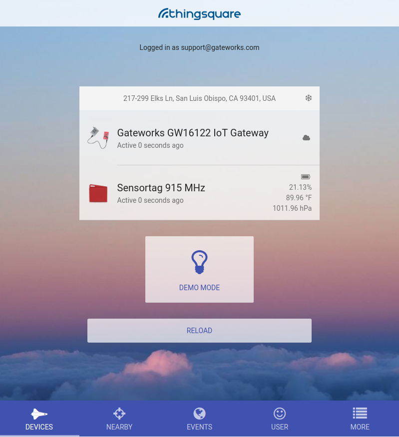
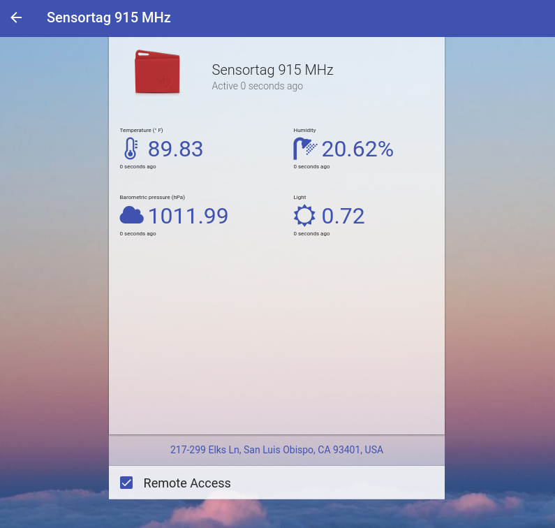
Thingsquare
Thingsquare is a software company that offers customized software for the chip on the GW16122, the Ti CC135x. This software allows for the use of a smartphone app to monitor and control sensors through the Thingsquare cloud/backend. A REST API is available as well.
A brief description of what is happening in the demo below:
- A Gateworks GW16122 is acting as the IoT Gateway on the Gateworks SBC
- The GW16122 exposes a few serial interfaces (/dev/ttyACM0 and /dev/ttyACM1) which are then used for the SLIP interface
- dnsmasq acts as a DNS server for the slip interface
- The sl0 uses PTP for the DNS
- The SLIP requires some routing and forwarding between interface sl0 and eth0
- The firmware on the GW16122 pushes data up to the Thingsquare cloud
- The CC1350 Sensor tag is reporting back to the Gateway and pushing it's information up to the cloud
Hardware required as noted here
Steps:
- Flash the GW16122 and sensor nodes with Thingsquare Firmware located here
- GW16122 Firmnware: CC1350 Launchpad Serial USB Access Point (US / 915 MHz)
- Sensor Firmnware: CC1350 Sensortag
- Insert GW16122 into a Gateworks SBC Mini-PCIe slot that has USB support
- Load Gateworks SBC Ubuntu 16.04 Software
- Install Ubuntu Xenial 16.04 with the instructions Ventana 16.04
- Confirm /dev/ttyACM0 and /dev/ttyACM1 exist on the Gateworks SBC in software
- Confirm an ethernet cable is connected to the Gateworks SBC connected to a LAN that has internet access via a WAN
- Install dnsmasq
apt-get install dnsmasq - Add the following lines to the end of the /etc/dnsmasq.conf file:
interface=sl0
listen-address=127.0.0.1
listen-address=172.16.0.1
- Create a script or add to /etc/rc.local to be ran after the board boots each time:
modprobe slip
stty -F /dev/ttyACM0 115200
sleep 3
slattach -L -s 115200 -p slip /dev/ttyACM0 &

sleep 10
ifconfig sl0 172.16.0.1 dstaddr 172.16.0.2
ifconfig sl0 mtu 600

echo 1 > /proc/sys/net/ipv4/ip_forward

iptables -t nat -A POSTROUTING -o eth0 -j MASQUERADE
iptables -A FORWARD -i eth0 -o sl0 -j ACCEPT
iptables -A FORWARD -i sl0 -o eth0 -j ACCEPT
systemctl start dnsmasq.service
- Utilize the Thingsquare website to connect both sensor and Gateway to cloud with the following instructions: http://www.thingsquare.com/docs/get-started-with-starter-kit/
- Important Note: Checking the box 'Remote Access' is important to connect the device to the Thingsquare backend and available when logging into the app/browser with user account
- You can use the website https://developer.thingsquare.com/web/ to access the devices from a PC browser. Create a Thingsquare account.
- Use the bottom menu icon, 'Nearby' to be sure you can discover the device on the LAN
Screenshots:


Troubleshooting:
- Verify traffic on sl0 interface with tcpdump
root@xenial-ventana:~# tcpdump -i sl0
tcpdump: verbose output suppressed, use -v or -vv for full protocol decode
listening on sl0, link-type RAW (Raw IP), capture size 262144 bytes
17:04:02.516758 IP 172.16.0.2.10323 > ec2-52-211-110-245.eu-west-1.compute.amazonaws.com.https: Flags [P.], seq 12805:13034, ack 371767140, win 500, length 229
17:04:02.682914 IP ec2-52-211-110-245.eu-west-1.compute.amazonaws.com.https > 172.16.0.2.10323: Flags [.], ack 229, win 54500, length 0
17:04:02.685640 IP ec2-52-211-110-245.eu-west-1.compute.amazonaws.com.https > 172.16.0.2.10323: Flags [P.], seq 1:102, ack 229, win 54500, length 101
17:04:02.941381 IP 172.16.0.2.10323 > ec2-52-211-110-245.eu-west-1.compute.amazonaws.com.https: Flags [P.], seq 229:330, ack 102, win 500, length 101
17:04:03.148806 IP ec2-52-211-110-245.eu-west-1.compute.amazonaws.com.https > 172.16.0.2.10323: Flags [.], ack 330, win 54500, length 0
17:04:12.109625 IP 172.16.0.2.10323 > ec2-52-211-110-245.eu-west-1.compute.amazonaws.com.https: Flags [P.], seq 330:479, ack 102, win 500, length 149
17:04:12.276629 IP ec2-52-211-110-245.eu-west-1.compute.amazonaws.com.https > 172.16.0.2.10323: Flags [.], ack 479, win 55500, length 0
17:04:18.591617 IP 172.16.0.2.10323 > ec2-52-211-110-245.eu-west-1.compute.amazonaws.com.https: Flags [P.], seq 479:580, ack 102, win 500, length 101
17:04:18.756148 IP ec2-52-211-110-245.eu-west-1.compute.amazonaws.com.https > 172.16.0.2.10323: Flags [.], ack 580, win 55500, length 0
17:04:18.772626 IP 172.16.0.2.10323 > ec2-52-211-110-245.eu-west-1.compute.amazonaws.com.https: Flags [P.], seq 580:649, ack 102, win 500, length 69
17:04:18.941914 IP ec2-52-211-110-245.eu-west-1.compute.amazonaws.com.https > 172.16.0.2.10323: Flags [.], ack 649, win 55500, length 0
^C
11 packets captured
11 packets received by filter
0 packets dropped by kernel
root@xenial-ventana:~#
- Verify dnsmasq is running:
systemctl status dnsmasq.service
- Verify dnsmasq is listening on the right address 172.16.0.1
root@xenial-ventana:~# netstat -tulpn
Active Internet connections (only servers)
Proto Recv-Q Send-Q Local Address           Foreign Address         State       PID/Program name
tcp        0      0 127.0.0.1:53            0.0.0.0:*               LISTEN      824/dnsmasq
tcp        0      0 172.16.0.1:53           0.0.0.0:*               LISTEN      824/dnsmasq
tcp        0      0 0.0.0.0:22              0.0.0.0:*               LISTEN      645/sshd
tcp6       0      0 ::1:53                  :::*                    LISTEN      824/dnsmasq
tcp6       0      0 :::22                   :::*                    LISTEN      645/sshd
udp        0      0 127.0.0.1:53            0.0.0.0:*                           824/dnsmasq
udp        0      0 172.16.0.1:53           0.0.0.0:*                           824/dnsmasq
udp        0      0 0.0.0.0:68              0.0.0.0:*                           584/dhclient
udp6       0      0 ::1:53                  :::*                                824/dnsmasq
root@xenial-ventana:~#
- Verify sl0 interface exists and is up:
root@xenial-ventana:~# ifconfig eth0 Link encap:Ethernet HWaddr 00:d0:12:9b:f2:af inet addr:172.24.22.173 Bcast:172.24.255.255 Mask:255.240.0.0 inet6 addr: fe80::2d0:12ff:fe9b:f2af/64 Scope:Link UP BROADCAST RUNNING MULTICAST MTU:1500 Metric:1 RX packets:8962 errors:0 dropped:0 overruns:0 frame:0 TX packets:483 errors:0 dropped:0 overruns:0 carrier:0 collisions:0 txqueuelen:1000 RX bytes:665276 (665.2 KB) TX bytes:58003 (58.0 KB) lo Link encap:Local Loopback inet addr:127.0.0.1 Mask:255.0.0.0 inet6 addr: ::1/128 Scope:Host UP LOOPBACK RUNNING MTU:65536 Metric:1 RX packets:172 errors:0 dropped:0 overruns:0 frame:0 TX packets:172 errors:0 dropped:0 overruns:0 carrier:0 collisions:0 txqueuelen:1000 RX bytes:13066 (13.0 KB) TX bytes:13066 (13.0 KB) sl0 Link encap:Serial Line IP inet addr:172.16.0.1 P-t-P:172.16.0.2 Mask:255.255.255.255 UP POINTOPOINT RUNNING NOARP MULTICAST MTU:600 Metric:1 RX packets:307 errors:0 dropped:0 overruns:0 frame:0 TX packets:345 errors:0 dropped:0 overruns:0 carrier:0 collisions:0 txqueuelen:10 RX bytes:42795 (42.7 KB) TX bytes:24061 (24.0 KB) - Verify you can ping www.google.com from the Gateworks SBC command line
References:
- Ti Thingsquare http://www.ti.com/ww/en/internet_of_things/Thingsquare-for-TI-IoT-development-kits.html
Programming the CC1350
The CC1350 of the GW16122 can be programmed a number of ways depending on your host machine.
Gateworks has tested both Windows (SmartRF Flash Programmer v2) and Linux (Uniflash) tools but specific instructions will be provided from the Linux perspective. However, the Windows Software may be easier and more reliable to use.
You will need to have installed the software detailed in the Set Up section in order to continue.
The Uniflash tool is linux compatible and has both a gui and command line interface. The gui program has an autodetect feature and is somewhat easier to use but the command line tool has the same functionality and is better suited for repeated tasks with constant configurations.
- Note that there doesn't appear to be a way to update the firmware on a running ARM based target. All of the methods we used to program the TiVa and CC1350 MCU's from a x86 host are not compatible with an ARM based system. This means that users will not be able to update firmware on running boards.
GUI Approach
- Connect a single GW16122 to the host machine (desktop/laptop) via mini-PCIe to USB adapter.
- Open the "Uniflash" application through a gui file manager from the uniflash_4.2 install directory, or via command line:
./uniflash_4.2/node-webkit/nw
- Select target device of CC1350F128
- Select connection of Texas Instruments XDS110 USB Debug Probe
- Click the "Start" button
In the Program tab, select the firmware file you wish to load. This is typically a .out file created via a Code Composer Studio Project and can be found in your workspace directory (default ~/workspace_v7/)
- Click the "Load Image" and "Verify Image" buttons and see the text console output on the bottom of the window for a green success message
It should also be mentioned that you can program your GW16122 directly from the Code Composer Studio IDE by creating a proper target configuration and then selecting "Debug". Most of the TI example projects will detail this procedure.
At this point you may want to power cycle your device.
Command Line Approach
- Navigate to your uniflash install directory
cd uniflash_4.2
- Run the installer providing a configuration and .out file as arguments, for example:
./dslite.sh --config=CC1350F128.ccxml ~/workspace_v7/collector_cc1350lp/collector_cc1350lp/collector_cc1350lp.out
The CC1350F128.ccxml file can be created via the uniflash gui or Code Composer Studio IDE. The contents of the file are provided in the collapsible text below for convenience.
CollapsibleStart(CC1350F128.ccxml)
<?xml version="1.0" encoding="UTF-8" standalone="no"?>
<configurations XML_version="1.2" id="configurations_0">
<configuration XML_version="1.2" id="configuration_0">
        <instance XML_version="1.2" desc="Texas Instruments XDS110 USB Debug Probe" href="connections/TIXDS110_Connection.xml" id="Texas Instruments XDS110 USB Debug Probe" xml="TIXDS110_Connection.xml" xmlpath="connections"/>
        <connection XML_version="1.2" id="Texas Instruments XDS110 USB Debug Probe">

                           <instance XML_version="1.2" href="drivers/tixds510icepick_c.xml" id="drivers" xml="tixds510icepick_c.xml" xmlpath="drivers"/>

                           <instance XML_version="1.2" href="drivers/tixds510cs_dap.xml" id="drivers" xml="tixds510cs_dap.xml" xmlpath="drivers"/>

                           <instance XML_version="1.2" href="drivers/tixds510cortexM.xml" id="drivers" xml="tixds510cortexM.xml" xmlpath="drivers"/>


                  <property Type="choicelist" Value="4" id="SWD Mode Settings">
            <choice Name="cJTAG (1149.7) 2-pin advanced modes" value="enable">
                <property Type="choicelist" Value="1" id="XDS110 Aux Port"/>
            </choice>
        </property>

                  <property Type="choicelist" Value="1" id="Power Selection">
            <choice Name="Probe supplied power" value="1">
                <property Type="stringfield" Value="3.3" id="Voltage Level"/>
            </choice>
            <choice Name="Target supplied power" value="0">
                <property Type="choicelist" Value="1" id="Voltage Selection">
                    <choice Name="User specified value" value="1">
                        <property Type="stringfield" Value="3.3" id="Voltage Level"/>
                    </choice>
                </property>
            </choice>
        </property>

                  <property Type="choicelist" Value="0" id="JTAG Signal Isolation"/>

            <platform XML_version="1.2" id="platform_0">
                <instance XML_version="1.2" desc="CC1350F128" href="devices/cc1350f128.xml" id="CC1350F128" xml="cc1350f128.xml" xmlpath="devices"/>
            </platform>
        </connection>
    </configuration>
</configurations>
References
- CC1350 Wiki
- Launch Pad Landing Page on Ti
- Ti Information regarding Contiki
- XDS110 User Guide
- TI 15.4-Stack - Linux Gateway Project Zero App Note
- TI Sub-1GHz E2E Forum
- CC1350 Bluetooth Software for use with iPhone App
CC1350STK Notes
The CC1350STK is a sensor node sold and designed by Ti. While similar to the Launch Pad, it is much smaller.
- Button 1 is the button on the edge furthest away from the JTAG headers. This is labeled as the 'Power' button.
- Button 2 is the button on the same edge as the JTAG headers. This is a 'user' button.
- There is no green LED on CC1350STK. There is only Green LED on CC2650STK and that function is for CC2650STK.
- Hex file to erase CC1350SensorTag_ExtFlashErase.hex
- Hex file for default factory image: CC1350SensorTag_BLE_All_v1_33.hex
- It's not possible to set the STK in factory restore by pushing buttons.
- The Ti Bluetooth iPhone app is missing the 1Ghz factory image in the list of available firmware.
- Files are placed here (typical installation path): *C:\Program Files (x86)\Texas Instruments\SmartRF Tools\BLE Device Monitor\firmware\cc1350\sensortag
- rfWsnDmNodeOad_US_CC1350STK_TI_CC1350F128-v1_06.hex
Attachments (8)
- gw16122webgui.png (49.0 KB ) - added by 6 years ago.
- GW16122.jpg (181.3 KB ) - added by 6 years ago.
- 16122range.png (2.4 MB ) - added by 6 years ago.
- gw16122diagram.png (1.0 MB ) - added by 6 years ago.
- thingsquare1.png (193.5 KB ) - added by 5 years ago.
- thingsquare2.png (149.9 KB ) - added by 5 years ago.
- 16122pins.png (97.4 KB ) - added by 4 years ago.
-
GW16122.PNG
(478.6 KB
) - added by 4 years ago.
GW16122
Download all attachments as: .zip