
| Version 38 (modified by , 4 years ago) ( diff ) |
|---|
GW16130 Iridium Satellite Modem
The GW16130 is a Mini-PCIe Satellite Modem that provides cost-effective, short burst satellite connectivity for asset tracking, fleet management, telemetry, oceanographic data, grid monitoring and Internet of Things (IoT) applications. The GW16130 features an Iridium 9603N satellite transceiver which allows two-way communications anywhere in the world with a clear line of sight to the sky. The Iridium network consists of 66 satellites and provides 24/7 world wide coverage. The 9603N module is used for short burst data packets (340bytes uplink, 270bytes downlink) and perfect for IoT remote sensor applications with minimal non-realtime data requirements. The GW16130 modem will work in a full size Mini-PCIe socket that includes a USB 2.0 interface. See the Gateworks website for suggested single board computers that can be used with this modem. Serial communications to the module is through an onboard FTDI USB to UART bridge. All power conditioning circuitry is contained on the board in addition to an u.Fl antenna connector for connecting an external satellite antenna. Note that an Iridium approved satellite antenna must be used when operating on the Iridium network. The GW16130 modem requires a monthly data plan which can be established with a number of 3rd party providers. Typical data charges are ~$20 USD per month with 12Kbytes of data included.

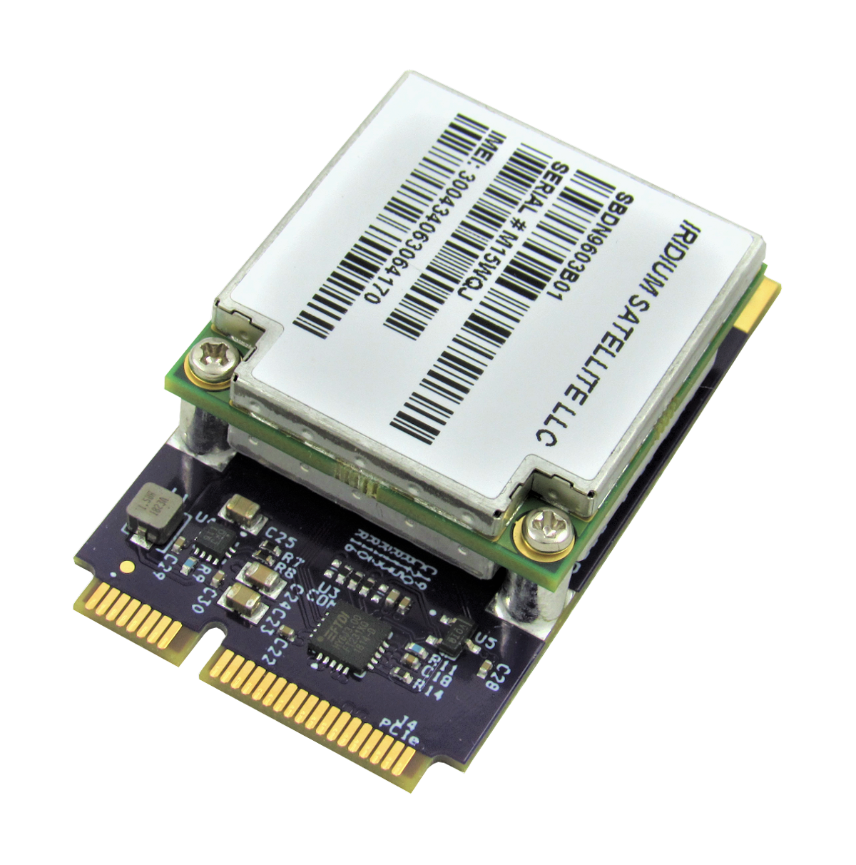
GW16130 = GW16127 Mini-PCIe carrier + Iridium 9603 modem module
Single Board Computer Support
The modem has been tested and verified on Gateworks SBCs in a Mini-PCIe slot with USB 2.0 routed. The modem is supported on a wide variety of software, as it works over AT commands using a USB to UART adapter. The FTDI USB to UART driver must be installed on the operating system, however, this is default on Gateworks BSPs. The GW16130 utilizes the FT231XQ USB to UART device.
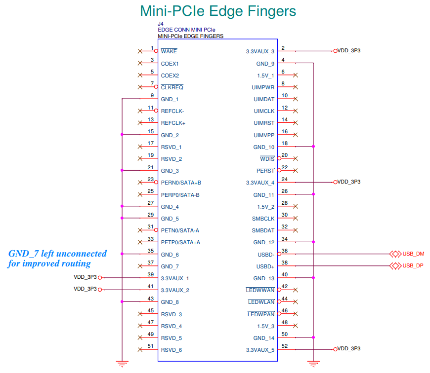
See below for the Mini-PCIe edge finger pinout on the GW16130. The USB signals are mapped to the standard pins specified in the Mini-PCIe specification (pins 36 & 38).

Data Providers and Modem Activation
Modems need to be activated using an approved Iridium carrier/provider.
During the activation, the modem is configured for the destination of the messages:
- Direct IP
- Email address
- Another modem
Some providers found on the internet, but not endorsed or approved by Gateworks:
- https://www.northernaxcess.com/sbd-short-burst-data-airtime-plans
- https://satellitephonestore.com/iridium-sdb
- https://www.satphonestore.com/airtime/iridium-sbd.html
- http://www.rock7mobile.com/products-rockblock-9603
- http://www.nalresearch.com/Airtime.html#Short%20Burst%20Data%20(Standard%20Plan)
Antenna
To comply with Iridium's module certification an approved Iridium antenna must be used with the GW16130.
Please see below recommended antennas:
- Taoglas Limited IAA.01.121111
- Digi-Key
- Note: Requires u.Fl to SMA pigtail, Gateworks Shop GW10036
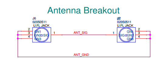
A small u.Fl patch cable (GW10135, included) is connected from the modem module to J6 or J7 (interchangeable) on the Mini-PCIe base board. The modem would then be connected to either J6 or J7, whichever is not used by the modem module. This is purely for convenience, if required, antenna can be connected directly to the modem module. See below schematic snippet.

- Antenna Characteristics
- Impedance = 50 Ohms nominal
- Gain (maximum) = 3dBi
- Polarization = RHCP
- VSWR (in band) = 1.5:1
- VSWR (out of band) = 3:1
Turning on Modem *REQUIRED*
An FTDI FT231XQ USB to UART Chip is used to communicate with the Iridium Satcom modem via its serial UART. The FT231XQ datasheet can be found here.

The FTDI GPIO pins control the modem:
- CBUS0: SAT_ON (input to modem; 10k pull-down)
- CBUS1: SAT_FND (output from modem)
- CBUS2: SAT_SUPPLY_OUT (output from modem)
- CBUS3: not connected
By default (for all GW16130 boards manufactured after Jul 8, 2020) the FTDI EEPROM is configured by Gateworks such that CBUS0 is configured to always drive a logic high level (DRIVE1) to enable the modem at powerup and the other CBUS pins are configured as GPIO.
If you wish to be able to disable the modem you can use the ftx_prog utility to alter the EEPROM configuration for CBUS0 and make it a GPIO then use either Linux gpiolib (/sys/class/gpio) as shown below or some other means (such as an application using libftdi) to manipulate it. If you change CBUS0 to a GPIO the modem will by default be disabled (due to the 10k pull-down on that signal) until you configure the GPIO to output a logic high.
The ftx_prog utility is an open source program that uses libftdi and can be easily built:
sudo apt-get install git build-essential gcc make libftdi-dev
git clone https://github.com/richardeoin/ftx-prog.git
cd ftx-prog
make
The following commands are used to configure the FTDI EEPROM such that the CBUS0 is a GPIO:
sudo ./ftx_prog --cbus 0 GPIO # configure CBUS0 as GPIO
And if you want to re-configure it to change it back to Drive_1 to make the modem always enabled at power-up:
sudo ./ftx_prog --cbus 0 Drive_1 # configure CBUS0 as always output high
You will need to either power-cycle your board or reload the ftdi_sio kernel module to make this take effect:
rmmod ftdi_sio
modprobe ftdi_sio
If CBUS0 is configured as GPIO you can use the following commands (on a 4.20 or newer kernel) to configure GPIO & enable the modem:
base=$(for i in $(ls -1d /sys/class/gpio/gpiochip*); do [ "ftdi-cbus" = "$(cat $i/label)" ] && cat $i/base; done)
[ "$base" ] || { echo "Error: could not find ftdi-cbus device"; }
echo $((base+0)) > /sys/class/gpio/export
echo out > /sys/class/gpio/gpio$((base+0))/direction
echo 1 > /sys/class/gpio/gpio$((base+0))/value # enable modem
echo $((base+1)) > /sys/class/gpio/export
echo in > /sys/class/gpio/gpio$((base+1))/direction
echo $((base+2)) > /sys/class/gpio/export
echo in > /sys/class/gpio/gpio$((base+2))/direction
Note that exporting the GPIO will fail if it was configured for 'Drive_1'.
Modem AT Commands
The Iridium SBD modems communicate via AT commands over the UART (default 19200 baud).
In a Linux system the UART mapping is dynamic. See the following for examples on determining the correct port mapping. Note these commands only work if there is a single FTDI device in the system.
If there is only a single FTDI device in the system, it typically will enumerate as /dev/ttyUSB0
AT Commands via picocom: (only works if there is one ftdi device being used in the system)
DEVICE=/dev/$(basename $(ls -d /sys/bus/usb/drivers/ftdi_sio/*/ttyUSB*))
picocom $DEVICE -b 19200 --omap lfcr
AT Commands via shell: (auto-magic device select script only works if there is one ftdi device being used in the system)
DEVICE=/dev/$(basename $(ls -d /sys/bus/usb/drivers/ftdi_sio/*/ttyUSB*))
stty -F $DEVICE 19200 ignbrk -brkint -icrnl -opost -onlcr -isig -icanon -iexten -echo -echoe -echok -echoctl -echoke
cat $DEVICE &
at() { echo -n -e "$1\r" > $DEVICE; }
at "AT+GMI" # Manufacturer Identification 'Iridium'
at "AT+GMM" # Model Identification 'IRIDIUM 9600 Family SBD Transceiver'
at "AT+GMR" # Revision details
at "AT+GSN" # serial number (IMEI)
at "AT+CSQ" # signal strength (0 to 5): '+CSQ:0' (where 5 is the best, as in 5 bars of service vs 0 bars of service
Additional commands:
- Send message on Modem (to destination configured in modem admin where modem is registered)
AT&K0 # Prepare
AT+SBDWT=Hello World #enter message as string
AT+SBDIX # Send message
+SBDIX: 0, 4, 0, 0, 0, 0 #Response saying it was successful
- Typically the first number should be 0 for success. To read more about the SBDIX response, read through one of the AT Command Documents
Troubleshooting
- If no AT commands are working, verify the modem is enabled using the FTDI CBUS GPIOs as described in the Turning on Modem section on this wiki page.
- Be sure the satellite antenna has a clear view of the sky, check the signal strength with the AT+CSQ
- If the module hangs/resets during a transmit verify your SBC can provide the needed power to the device. When transmitting the modem can draw over 6.5W which can exceed the limits of some SBCs. Gateworks SBCs have been designed to handle large power transients such as these.
Mechanicals
Dimensions: 30.00 wide x 50.95 long x 11.60 mm tall (1.18 x 2.00 x 0.46 in)
Note that the GW16130 will not fit inside of a standard Gateworks Indoor Enclosure.
GW16130 on Non-Gateworks Platforms
Note this is not supported by Gateworks, but here are some notes:
- Power: Initial testing on a Windows 10 Dell Laptop revealed the modem with a USB to Mini-PCIe adapter was detected and AT commands could be sent. Upon trying to transmit a packet, the serial connection with the modem was lost. It is assumed there was not enough power out of the 500mA USB port to support the transmit.
- GPIO: It is very important to ensure the modem is enabled with the FTDI CBUS GPIOs as described in the Turning on Modem section on this wiki page.
Reference Links
- Iridium 9603 https://www.iridium.com/products/iridium-9603/
- Iridium 9603 AT Commands https://www.google.com/search?q=iridium+9603+at+commands
- Drifting Buoy Project using 9603 http://mdbuoyproject.wixsite.com/default
- Gateworks GW16130 datasheet http://www.gateworks.com/product/item/gw16130-mini-pcie-satellite-modem
- FTDI Drivers (FT231XQ device is used) https://www.ftdichip.com/FTDrivers.htm
- Using FTDI D2xxx Drivers under Windows https://www.youtube.com/watch?v=GmBGMWBfMmA
- FTDI Prog Tool for Windows https://www.ftdichip.com/Support/Utilities.htm#FT_PROG
- FTDI Bit Bang Modes for FT-X https://www.ftdichip.com/Support/Documents/AppNotes/AN_373%20Bit-Bang%20Modes%20for%20the%20FT-X%20Series.pdf
Attachments (6)
-
GW16130_Pinout.png
(87.9 KB
) - added by 5 years ago.
Mini-PCIe Edge Finger Pinout
-
GW16130.png
(1.0 MB
) - added by 5 years ago.
GW16130 Mini-PCIe Satellite Modem
- gw16127-antenna.png (19.5 KB ) - added by 5 years ago.
- 16130-block-diagram.png (37.9 KB ) - added by 5 years ago.
-
ftx_prog
(26.6 KB
) - added by 5 years ago.
ftx_prog compiled for Newport Ubuntu Bionic with 4.14 kernel
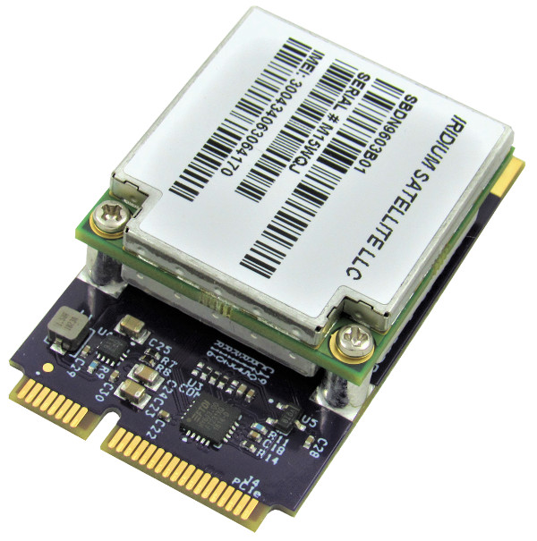
- GW16130.jpg (96.4 KB ) - added by 5 years ago.
Download all attachments as: .zip