
| Version 67 (modified by , 5 months ago) ( diff ) |
|---|
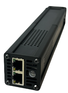
GW3089 GBlade Server Blade


Product Information
Gateworks main website product information and datasheet can be found here: Link
Getting Started
The GBlade is pre-installed with Ubuntu Linux. You must access the serial console for initial configuration. The following steps are required when bringing up new units.
Power Gblade over active PoE
Isolated 802.3at 1GbE active PoE is supported on the bottom 1GbE Ethernet port. The Gateworks GW10144 802.3at PoE power supply/inserter can be used to power individual units and/or during development. See link here for info on GW10144: Tycon Inserter. Typical power consumption is around 10-13W without any additional cards plugged into the NVME socket. For rackmount applications a 802.3at PoE switch is recommended. To use the 10GbE port for PoE powering the device, please contact Gateworks Sales.
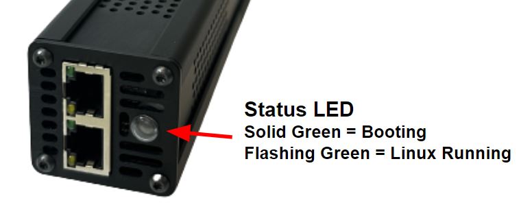
Status LED Indicator
Once power is applied and the bootloader start loading the OS, the LED status indicator on the frontplate will turn on solid green. Once Linux is fully loaded this LED will flash (heartbeat) indicating that the OS has fully loaded.
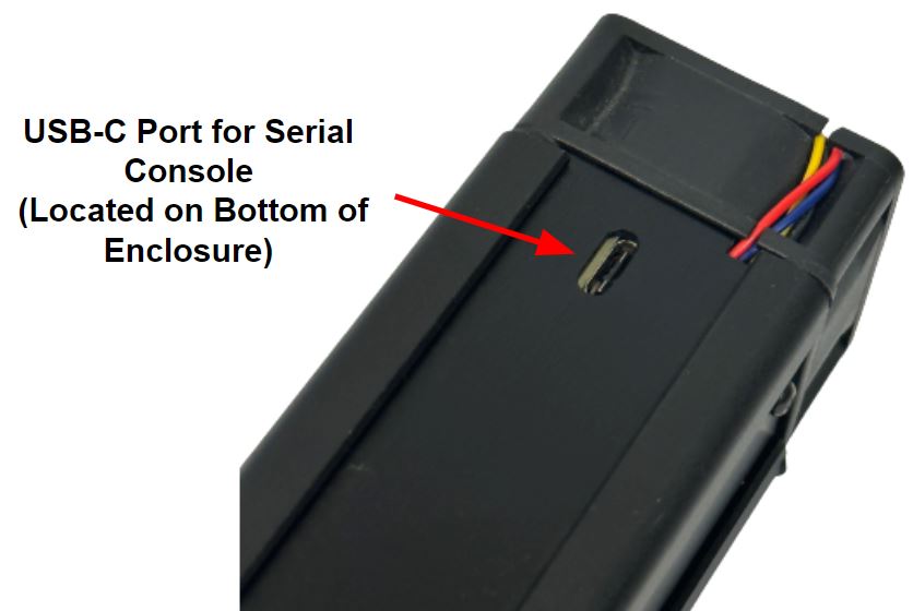
Serial Console Access
Once the unit is powered, the GBlade serial console can be accessed through the type C USB port through a cable to a desktop/laptop PC. The serial console uses an industry standard FTDI FT2232HQ USB to Serial/JTAG converter IC and will show up as a /dev/ttyUSBx device in Linux and can be accessed through a terminal program with the baud rate of 115,200. For other operating systems, such as Windows, virtual COM port (VCP) drivers can be found here: Link.
jammy-malibu login: root
Password: root

Example:
sudo screen /dev/ttyUSB1 115200,cs8
SSH Enabling
The default Ubuntu BSP has SSH disabled. If access over the management port is desired the user must enable SSH using the serial console. See instructions below.
The openssh-server package provides an ssh daemon suitable for secure shell (ssh) and secure copy (scp):
apt-get install openssh-server
To enable root ssh capability, which is disabled by default, do the following:
Edit /etc/ssh/sshd_config, and make sure the following line is commented out:
PermitRootLogin prohibit-passwordJust below it, add the following line:
PermitRootLogin yesThen reload SSH config:
service ssh reload
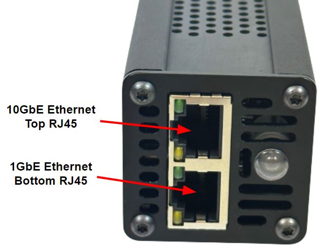
Connecting Ethernet
There are two Ethernet ports, 1GbE (management) and 10GbE (high speed data).
- (eth1) 1GbE RGMII port is on the bottom (PoE by default) - Note this interface is not enabled in the default Linux installation and will need to be enabled if user wants to use this interface for both power and management.
- (eth0) 10GbE XFI port is on the top - This port is brought up with DHCP enabled in the default Linux installation.

- Installing and Customizing Software
Any server software (LAMP stack, etc) can then be installed using the Ubuntu package manager.
apt-get update
apt-get install {your package}
USB Port
The Type-C USB port is only for serial console and JTAG access. This port will not work as a standard USB port. See serial console access above for more information.
NVME Socket
The GBlade contains a M.2 2280 PCIe Gen 3 x4 lane socket that can be used to support NVME drives, accelerator cards and radio cards (ie. AI accelerators, SDR radios, etc..). For volume orders contact sales for pre-installed options.
To load your own NVME drive you will need to be opened up the enclosure. Here are the steps to open the enclosure and access the NVME socket.
- Remove the four frontplate screws using a T8 Torx driver.
- Remove the frontplate and move to the side. Note the LED cable does not need to be removed.
- Slide out the side plate on the backside of the board (this is the side that the LED cable is mounted on).
- The M.2 NVME socket should now be visible and a drive can be inserted. Secure the drive to the PEM towards the front of the unit and reinstall the frontplate making sure the LED cable does not get pinched by any of the plates.
- The NVME drive should now show up as /dev/nvme0 and /dev/nvme0n1 respectively in Linux.
Example NVME speed tests with a Samsung 980 drive (~ 3.1 GB/s)
Welcome to Buildroot
buildroot login: root
# lspci -n; lspci -s 1:00.0 -vvv | grep Lnk; dd if=/dev/nvme0n1 of=/dev/null bs=
32M count=100 iflag=direct
00:00.0 0604: 11ab:0110
01:00.0 0108: 1987:5013 (rev 01)
                LnkCap: Port #1, Speed 8GT/s, Width x4, ASPM L1, Exit Latency L1 unlimited
                LnkCtl: ASPM Disabled; RCB 64 bytes, Disabled- CommClk+
                LnkSta: Speed 8GT/s, Width x4
                LnkCap2: Supported Link Speeds: 2.5-8GT/s, Crosslink- Retimer- 2Retimers- DRS-
                LnkCtl2: Target Link Speed: 8GT/s, EnterCompliance- SpeedDis-
                LnkSta2: Current De-emphasis Level: -6dB, EqualizationComplete+ EqualizationPhase1+
                LnkCtl3: LnkEquIntrruptEn- PerformEqu-
100+0 records in
100+0 records out
3355443200 bytes (3.4 GB, 3.1 GiB) copied, 1.07257 s, 3.1 GB/s
# dd if=/dev/nvme0n1 of=/dev/null bs=1M count=10k iflag=direct
10240+0 records in
10240+0 records out
10737418240 bytes (11 GB, 10 GiB) copied, 3.79569 s, 2.8 GB/s
LED Programming
A front panel status LED has been provided to indicate the status of the unit. This LED is bidirectional and can be programmed for red or green color. When power is applied, the LED will be a solid green. The LED will present a green heartbeat pattern is shown once the board is booted into Linux.

To disable the heartbeat LED:
root@jammy-malibu:~# echo none > /sys/class/leds/green\:heartbeat/trigger #disable default green heartbeat
root@jammy-malibu:~# echo 255 > /sys/class/leds/red\:status/brightness #set LED to solid RED
To see more Linux LED examples, see here: linux/led
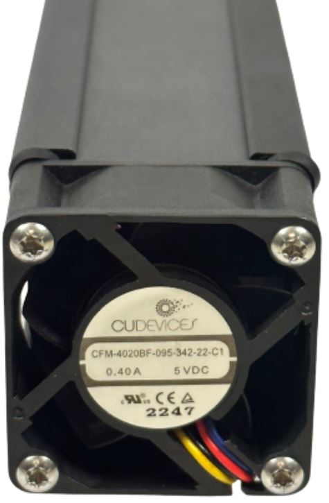
Thermal Considerations

The GW3089 uses the industrial temperature quad core Marvell CN9130 processor rated at 2.2GHz. The Tjunction rating for the processor is -40C to +105C. The GW3089 enclosure contains a built in CUI fan (model CUI CFM-4020BF-095-342-22) to keep the unit cool and provide airflow to the processor. When the unit first boots, the fan will turn on to full speed and then once Linux starts it will be under thermal control based on the processor's AP core temperature.
The fan runs at specific set points. The trip points are set at 50C, 60C and 80C (as shown in the device tree here). Note also the processor will throttle down if the fan isn't able to achieve proper cooling with the fan.
The PWM values for the four default set points are as follows:
- Fan Off < 50C
- Fan On 40% PWM = 50C to 60C
- Fan On 67% PWM = 60C to 80C
- Fan On 100% PWM > 80C
These can be adjusted through the device tree if required.
Fan specifications:
- Operating Voltage: 5VDC
- Typical Power Consumption: 1.45W
- Typical RPM: 9500 RPM, Min 8550, Max 10450
- Typical CFM: 11.88
- Typical Noise: 34.2 dBA
- MTBF: Typ. 70K Hours @ +40C
- Operating Temp: -10C to +70C
- Dual Ball Bearing
- Auto Restart Protection
- Polarity Protection
- Soft Start
- Tachometer Signal
- PWM Control
- Safety Approvals: UL, cUL, TUV, CE
- RoHS
Temperature Monitoring
The CPU and 10GbE Phy have passive heatsinks to allow better cooling on these devices. Typical CPU temperature rise is around 8 degrees over ambient when running a moderate load.
When installing M.2 cards in the GW3089 make sure to take cooling into consideration. Most NVME and AI accelerators recommend some type of heatsink. The narrow width of the GW3089 enclosure will only allow around a 8mm or less tall heatsink on the M.2 card (depending on height of devices on the card). When installing heatsinks make sure to align the fins to maximize cooling with the air flowing from the front to rear of the enclosure. Some low cost, small copper heatsinks for M.2 cards can be found here: Link
The GW8901 uses standard Linux cooling-maps, thermal-zones and the pwm-fan driver. There are several temperature sensors on the board, identified as 'thermal_zones'. These are shown in Linux under /sys/class/thermal:
root@jammy-malibu:~# ls -la /sys/class/thermal/
total 0
drwxr-xr-x  2 root root 0 Jun 27 18:28 .
drwxr-xr-x 62 root root 0 Jun 27 18:28 ..
lrwxrwxrwx  1 root root 0 Jun 27 18:28 cooling_device0 -> ../../devices/virtual/thermal/cooling_device0
lrwxrwxrwx  1 root root 0 Jun 27 18:28 cooling_device1 -> ../../devices/virtual/thermal/cooling_device1
lrwxrwxrwx  1 root root 0 Jun 27 18:31 cooling_device2 -> ../../devices/virtual/thermal/cooling_device2
lrwxrwxrwx  1 root root 0 Jun 27 18:28 thermal_zone0 -> ../../devices/virtual/thermal/thermal_zone0
lrwxrwxrwx  1 root root 0 Jun 27 18:28 thermal_zone1 -> ../../devices/virtual/thermal/thermal_zone1
lrwxrwxrwx  1 root root 0 Jun 27 18:28 thermal_zone2 -> ../../devices/virtual/thermal/thermal_zone2
lrwxrwxrwx  1 root root 0 Jun 27 18:28 thermal_zone3 -> ../../devices/virtual/thermal/thermal_zone3
lrwxrwxrwx  1 root root 0 Jun 27 18:28 thermal_zone4 -> ../../devices/virtual/thermal/thermal_zone4
lrwxrwxrwx  1 root root 0 Jun 27 18:28 thermal_zone5 -> ../../devices/virtual/thermal/thermal_zone5
An example temperature for thermal_zone0 would be 60738, or 60738/1000=60.738 degrees Celsius:
root@jammy-malibu:~# cat /sys/class/thermal/thermal_zone0/temp
60738
The zones are labeled below. The AP stands for application processor, or the main CPU, with a sensor for each core of the quad core CPU. The CP0 stands for 'co-processor'.
root@jammy-malibu:~# cat /sys/class/thermal/thermal_zone*/type
ap-thermal-ic
ap-thermal-cpu0
ap-thermal-cpu1
ap-thermal-cpu2
ap-thermal-cpu3
cp0-thermal-ic
Fan tachometer / tach rpm:
The fan tachometer can be monitored using the following command:
root@jammy-malibu:/sys/class/hwmon/hwmon0# cat fan1_input
9510
Gateworks System Controller
The Gateworks System Controller manages things like the real time clock, voltage rails, fan PWM, etc. and more information can be found here: gsc
Software
The GW3089 is part of the Gateworks Malibu family of SBCs.
Malibu Software is comprised of many pieces, including the following:
- GSC (Gateworks System Controller) Firmware
- Boot Firmware (ARM Trusted Firmware, DDR controller Firmware, U-Boot Bootloader)
- Operating System (including kernel / rootfs)
An Ubuntu based OS is pre-installed on all Malibu boards before they ship. See the following link for the latest pre-built image:
Additional links available here:
- Main Malibu Wiki Page
- Malibu BSP Page
- Malibu Boot Firmware (up to and including the Bootloader)
- GSC Firmware
- Main Ubuntu Page
- Webmin Installation Page
- GW3089 Device Tree (provides info on hardware connections) - Device Tree
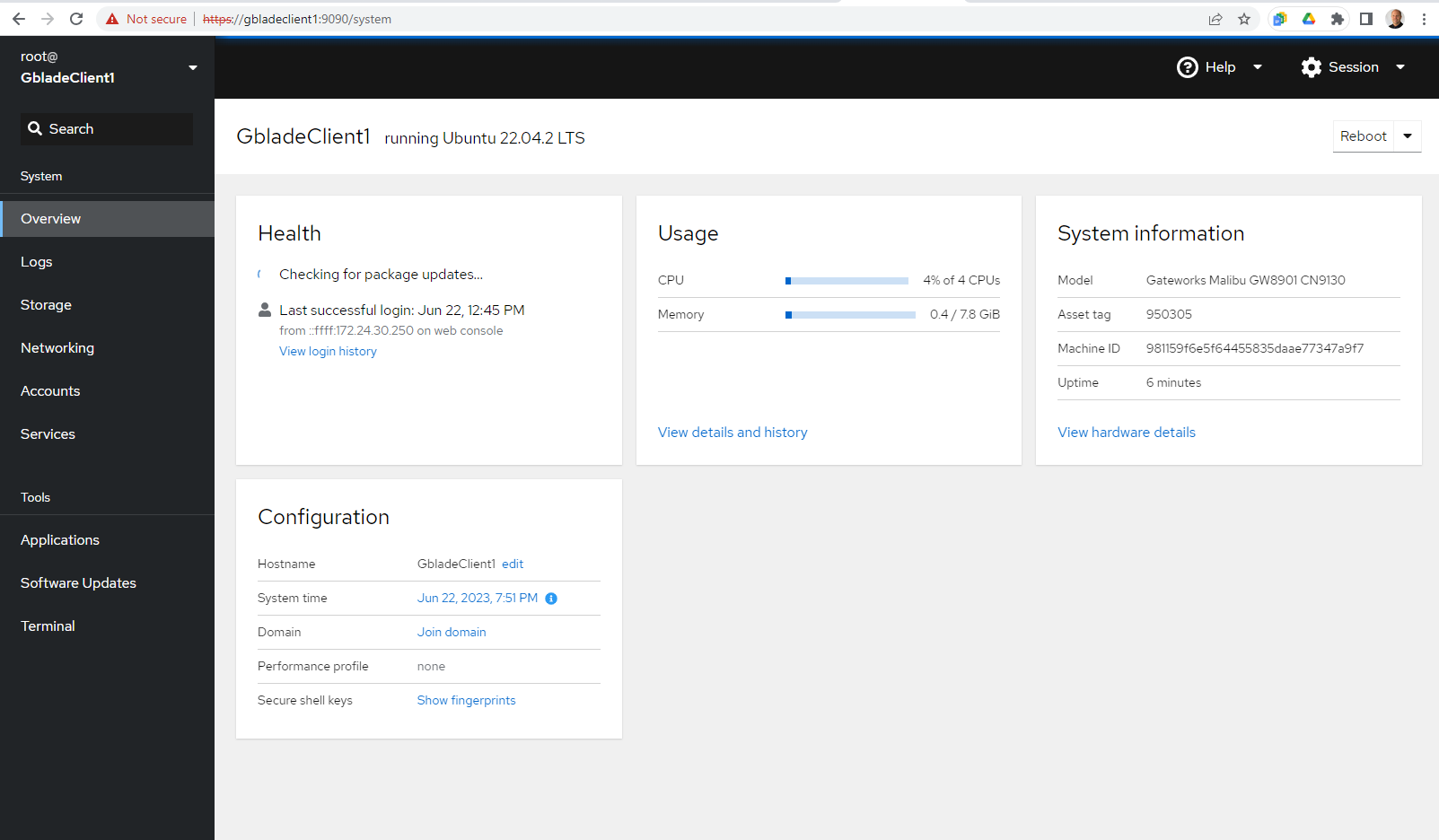
Cockpit Web Console

Cockpit is a nice user friendly web based administrator console that allows users to configure and manage remote servers. To install on the GBlade server use the following commands:
sudo apt install cockpit
sudo systemctl enable cockpit
sudo systemctl start cockpit
Once installed it can be accessed by a browser on the network at the following url:
https://<ip address>:9090
or
https://<localhost>:9090
Where localhost is the host name of the computer as set in the /etc/hostname file.
For more info on using Cockpit see the following link: Cockpit
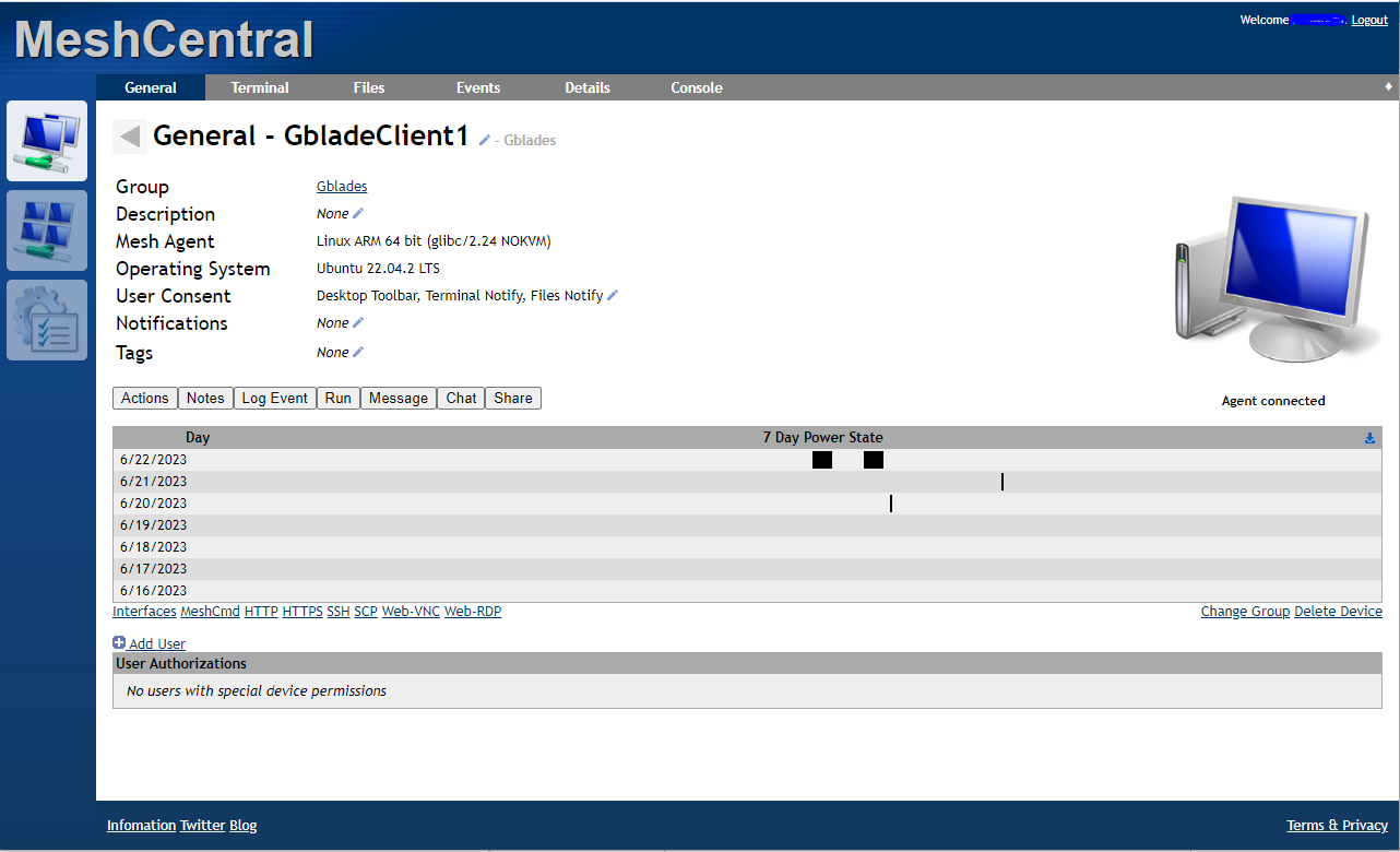
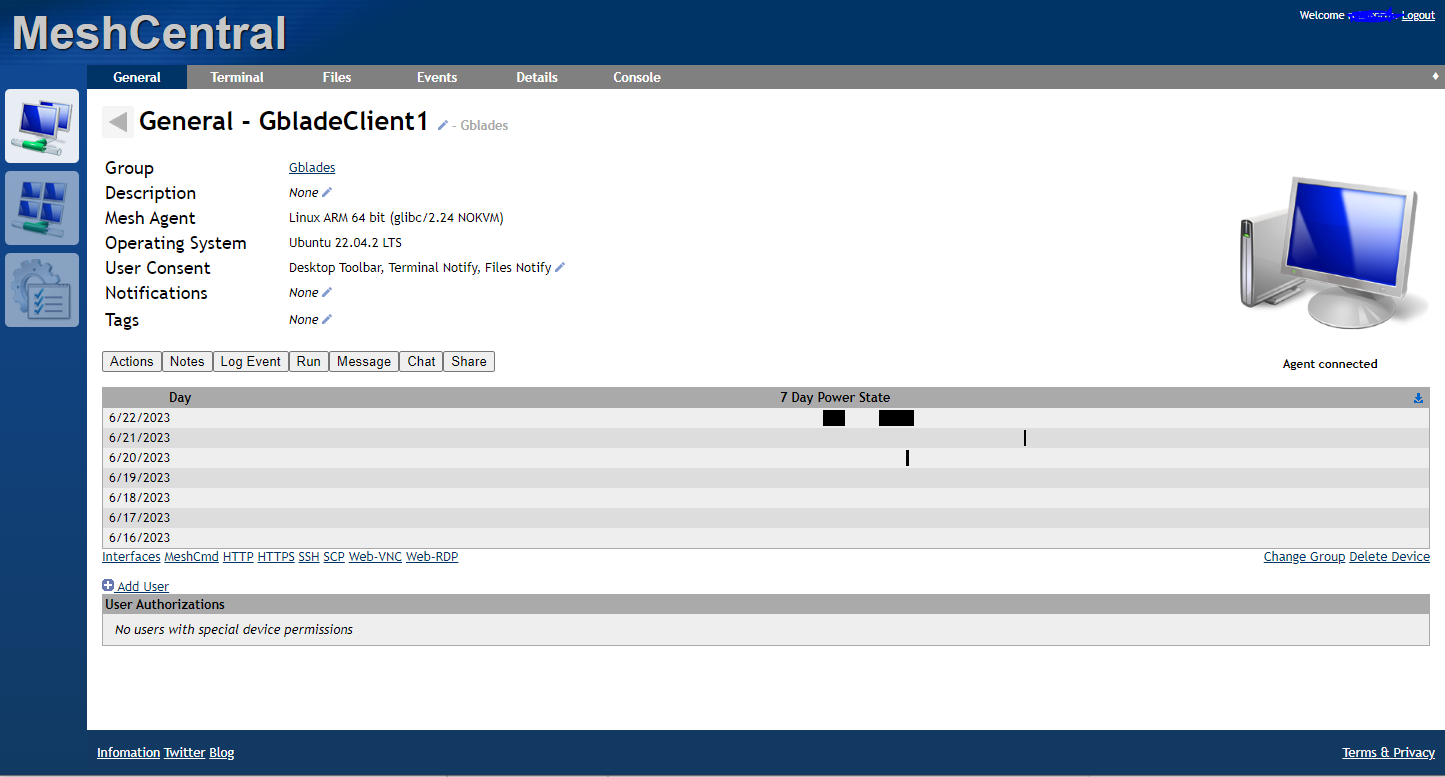
MeshCentral Remote Management

MeshCentral is an opensource, multi-platform, self-hosted, feature packed remote management applications. It allows for remote access to your GBlades.
See the following link for instructions on using and installing: Link
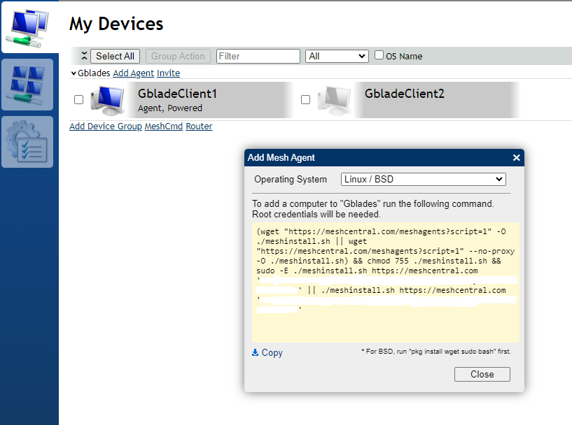
For a quick trial without installing the host software, you can create a free "Public Server Account" on the MeshCental website and then add clients to this account.
To install the client agent on a GBlade, click the "Agent" link under my devices tab, select "Linux/BSD" operating system and then copy the command line code from the popup box and run it from your command line on the GBlade. After completion, the GBlade will show up as a device in the MeshCentral dashboard.
Example command line code (note keys have been edited out):
(wget "https://meshcentral.com/meshagents?script=1" -O ./meshinstall.sh ||
wget "https://meshcentral.com/meshagents?script=1" --no-proxy -O ./meshinstall.sh)
&& chmod 755 ./meshinstall.sh && sudo -E ./meshinstall.sh https://meshcentral.com
'xxxxxxxxxxxxx' || ./meshinstall.sh https://meshcentral.com 'xxxxxxxxxxxxxx'

TPM / Crypto
See tpm
JTAG Programming & Firmware/OS Update
The GW3089 incorporates onboard a USB to JTAG FTDI chip to allow JTAG programming of the unit without the requirement for a separate JTAG dongle (GW16099) which is typically used on other Gateworks SBCs.
At this time, the GW3089 JTAG software is under development so for initial programming please see the following link on updating from a TFTP server: malibu/firmware. Check back for future JTAG software releases which will be posted here. Note that loading software over JTAG can take a significant amount of time so we recommend only using JTAG to load the bootloader and then using a TFTP server to load the Ubuntu image which can be quite large.
Enclosure
The GW3089 anodized enclosure uses the following screws for securing the board, fan and frontplate.
- Frontplate = Torx T8 Head, M3 x 8mm
- Fan = Torx T10 Head, M3 x 25mm
- Board standoffs = Hex 1.5mm Head M2.5 x 5mm
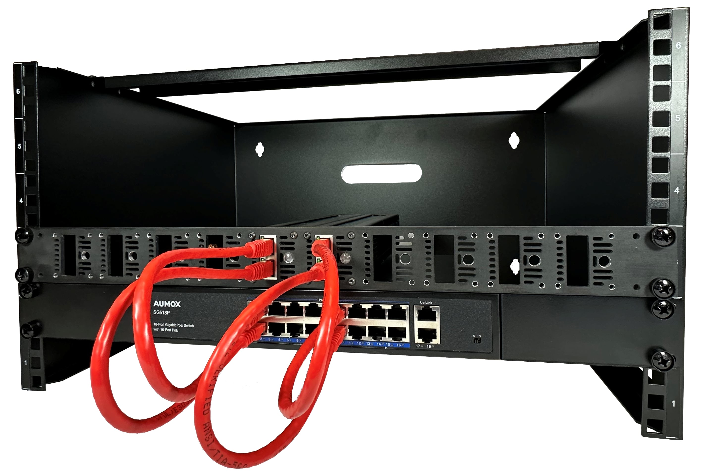
1U Rack Frontplate
A standard 1U rack frontplate is available to install QTY 10 GBlade servers in a rack mount scenario. The 1U plate part number is GW3090. Contact sales@… to purchase. See the following instructions for installing individual Gblades into the 1U frontplate:
- Remove the four frontplate screws using a T8 Torx driver.
- Remove the LED cable from the frontplate. Note the LED has a rear socket and a front lens. Gently pull the rear socket to separate from the front lens. Note there is a small rubber washer on the front lens which should be removed when installing in the thicker metal 1U frontplate.
- Move the unit to behind the 1U plate in the location that it will be installed and re-attach the LED cable by inserting the LED lens from the front side and pushing the socket onto it from the rear.
- Attach the unit to the 1U frontplate using the four Torx screws that held the original frontplate.
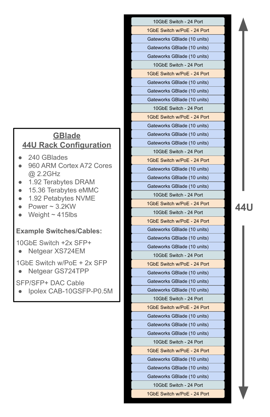
Server Rack Configuration
Below is an example configuration to fit over 240 GBlades in a 44U rack utilizing 24 port GbE/PoE+ switches and 24 port 10GbE switches.

Wireless & Modems
Wireless & modems were not intended for this ethernet connected blade server.
Attachments (11)
- ethernet.JPG (41.0 KB ) - added by 13 months ago.
- fan.JPG (37.9 KB ) - added by 13 months ago.
- GW3089.png (69.1 KB ) - added by 13 months ago.
- LED.JPG (23.6 KB ) - added by 13 months ago.
- serial.JPG (34.0 KB ) - added by 13 months ago.
- gw3090rack.jpg (362.5 KB ) - added by 13 months ago.
- cockpit.png (88.8 KB ) - added by 11 months ago.
- meshcentral.png (144.8 KB ) - added by 11 months ago.
- meshcentral1.png (144.7 KB ) - added by 11 months ago.
- meshcentralagent.png (79.4 KB ) - added by 11 months ago.
-
GBladerack.png
(270.1 KB
) - added by 5 months ago.
Sample GBlade full rack configuration
Download all attachments as: .zip