
| Version 10 (modified by , 6 years ago) ( diff ) |
|---|
UART Communication
This page gives some tips and tricks regarding serial communcation.
Gateworks boards often have connectors available for either RS232 or TTL level UART with and without hardware handshaking. Refer to the board specific hardware manual for pinout details.
Cables are available from Gateworks in the online shop:
- GW10001 10 pin IDC header to DB9
- GW10019 DB9 Gender Changer
- GW10005 DB9 male to DB9 female 6ft cable
Linux serial port devices
Serial UARTS will be represented as /dev/tty* devices depending on the CPU architecture.
The following table describes the various on-board UARTs for standard Gateworks products. Please consult the board specific hardware user manual for additional details:
| Family | Board | HW Dev | SW Dev | Function |
|---|---|---|---|---|
| Newport | GW630x/GW640x | UART0 | ttyAMA0 | console: 3.3V TTL J12 |
| UART1 | ttyAMA1 | GPS | ||
| UART2 | ttyAMA2 | RS232/RS485 J12 1 | ||
| UART3 | ttyAMA3 | RS232 J12 1 | ||
| Ventana | GW51xx | UART1 | ttymxc0 | GPS |
| UART2 | ttymxc1 | console: 3.3V TTL JTAG J10/J11 | ||
| UART5 | ttymxc4 | TTL J11 | ||
| GW52xx | UART1 | ttymxc0 | RS485/CAN/TTL J12 / RS232 J10 | |
| UART2 | ttymxc1 | console: 3.3V TTL JTAG J14 / RS232 J10 | ||
| UART5 | ttymxc4 | GPS | ||
| GW53xx | UART1 | ttymxc0 | RS485/CAN/TTL J11 / RS232 J12 | |
| UART2 | ttymxc1 | console: 3.3V TTL JTAG J14 / RS232 J12 | ||
| UART5 | ttymxc4 | GPS | ||
| GW54xx | UART1 | ttymxc0 | RS485 J13 / RS232 J15 | |
| UART2 | ttymxc1 | console: 3.3V TTL JTAG J17 / RS232 J15 | ||
| UART5 | ttymxc4 | GPS | ||
| GW551x | UART2 | ttymxc1 | console: exp 3.3V TTL J3 | |
| UART3 | ttymxc2 | exp 3.3V TTL J3 | ||
| GW552x | UART2 | ttymxc1 | console: 3.3V TTL JTAG J7 | |
| UART3 | ttymxc2 | exp 3.3V TTL J5 | ||
| UART5 | ttymxc4 | exp 3.3V TTL J5 | ||
| GW553x | UART2 | ttymxc1 | console: 3.3V TTL JTAG J11 | |
| UART3 | ttymxc2 | exp 3.3V TTL JTAG J10 | ||
| UART4 | ttymxc3 | GPS | ||
| UART5 | ttymxc4 | exp 3.3V TTL JTAG J10 | ||
| GW16111 | UART2 | ttymxc1 | console: 3.3V TTL JTAG J8 / RS232 J16 / RS485 J20 | |
| UART3 | ttymxc2 | RS232 J16 | ||
| Laguna | GW2380/2/3 | UART0 | ttyS0 | console: 3.3V TTL JTAG J2 / 3.3V TTL J4 |
| UART1 | ttyS1 | GPS | ||
| UART2 | ttyS2 | UART: 3.3V TTL J8 | ||
| GW2387 | UART0 | ttyS0 | console: 3.3V TTL JTAG J3/J7 / RS232 J13 | |
| UART1 | ttyS1 | RS232 J13 / 3.3V TTL J7 | ||
| UART2 | ttyS2 | GPS | ||
| GW2388 | UART0 | ttyS0 | console: 3.3V TTL JTAG J8 / RS232 J21 | |
| UART1 | ttyS1 | RS232 J21 | ||
| UART2 | ttyS2 | GPS | ||
| GW2391 | UART0 | ttyS0 | console: 3.3V TTL JTAG J1 / RS232 J15 | |
| UART1 | ttyS1 | RS232 J15 | ||
| UART2 | ttyS2 | GPS | ||
| Rincon | GW2361 | UART0 | ttyS0 | console: 3.3V TTL JTAG J2 |
| UART1 | ttyS1 | RS232 J7 | ||
| UART2 | ttyS2 | RS485 J6 | ||
| Cambria | GW2350 | UART0 | ttyS0 | console: 3.3V TTL JTAG J1/J10 |
| UART1 | ttyS1 | GPS | ||
| UART2 | ttyS2 | RS485 J6 | ||
| GW2358 | UART0 | ttyS0 | console: 3.3V TTL JTAG J10 / RS232 J17 | |
| UART1 | ttyS1 | GPS | ||
| UART2 | ttyS2 | RS485 J3 | ||
| Avila | GW2347 | UART0 | ttyS0 | console: 3.3V TTL JTAG J2 / RS232 J5 |
| UART1 | ttyS1 | UART: RS232 J3 | ||
| GW2348 | UART0 | ttyS0 | console: 3.3V TTL JTAG J7 / RS232 J13 | |
| UART1 | ttyS1 | UART: RS232 J6 | ||
| GW2355 | UART0 | ttyS0 | console: 3.3V TTL JTAG J3 / RS232 J5 | |
| UART1 | ttyS1 | GPS | ||
| GW2357 | UART0 | ttyS0 | console: 3.3V TTL JTAG J2 / RS232 J6 | |
| UART1 | ttyS1 | UART: RS232 J36 |
- Depends on software configuration
Baudrates
The maximum baudrate supported depends on the product family and sometimes whether or not you are using TTL or RS232 as at times a transceiver may limit the stream to below 250000 (consult the hardware manual). A safe and typical baudrate is 115200.
Flow control
Flow control refers to hardware or software handshaking that can tell a transmitter when its ok to send more data.
Hardware flow control is typically via RTS/CTS (request-to-send / clear-to-send) or via DTR/DSR (data-terminal-ready / data-set-ready). Depending on the board and port used you may be able to use hardware flow control.
Software flow control uses a specific character for start and stop and therefore cannot be used in binary data transfer.
Take care to set flow control properly. Typically this is done in Linux with the stty application. For example to disable the first UART's flow control on an IMX6 based Ventana product:
stty -crtscts -F /dev/ttymxc0
Serial Port Types (DCE vs DTE)
The Data Communication Equipment (DCE) pin assignments permit direct connection to a standard Data Terminal Equipment (DTE) PC running terminal emulation software. The inputs and outputs are swapped between DCE and DTE. Please pay careful attention to the connector pinout of any UART from the board's hardware user manual, specifically the TX/RX/RTS/CTS pin's direction (input vs output) to ensure proper interconnect with off-board equipment.
In certain scenarios, a null modem cable may be needed Null Modem Information
Please read more about the RS232 Specification here
Linux serial Console
There are times when one may not care about serial Linux console because the serial port is desired for other uses.
By default the Gateworks bootloader's configure one of the board's UARTs for serial console. This can be disabled by changing the bootargs in the bootloader:
- Example: Laguna uboot
setenv bootargs console= root=/dev/mtdblock3 rootfstype=squashfs,jffs2 noinitrd
saveenv
- Example: Ventana uboot:
setenv console null
saveenv
If using Yocto or a more traditional Linux based OS, you may need to take additional steps to disable the OS enabling the serial port for a Login terminal by removing the line with that serial port from /etc/inittab .
The bootloader will still output data upon power up - see below.
Bootloader Serial Console
If you wish to disable the bootloader's use of the serial port, you will need to recompile the bootloader.
Notes:
- For Lagunu u-boot-2008.10 modify CONFIG_CONS_INDEX in include/configs/cavium_cns3000*.h setting it to a non-existent port.
- Define CONFIG_SILENT_CONSOLE to enable support for silent mode (must custom compile bootloader as discussed on the wiki here)
- Set the u-boot envvar silent to disable some u-boot output
- One should probably tweak the bootdelay to 1 second (or turn it off)
- One can still interrupt u-boot by pressing the specified key (you won't see output, but your input will be processed)
Hardware Flow Control
A few Gateworks products that provide TTL level and/or RS232 serial can optionally provide hardware flow control via RTS# and CTS# pins. In this configuration. All Gateworks products present serial from the Data Terminal Equipment (DTE) perspective where TX and RTS are outputs, and RX and CTS are inputs with one exception:
- Ventana UART's are in DCE mode by default however TX is still an output and RX is an input. Therefore Ventana UART's with flow control are pinned out as follows:
- TX (output)
- RX (input)
- RTS (input)
- CTS (output)
RS232
RS-232 is a standard for serial communication transmission of data. The most important aspects of the spec are:
- defines electical signal characteristics such as voltage levels, signalling rate, timing and slew-rate of signals
- mechanical characteristics such as pinouts
Many Gateworks boards have RS232 support (not to be confused with TTL level UART support which has different voltage and signalling specifications).
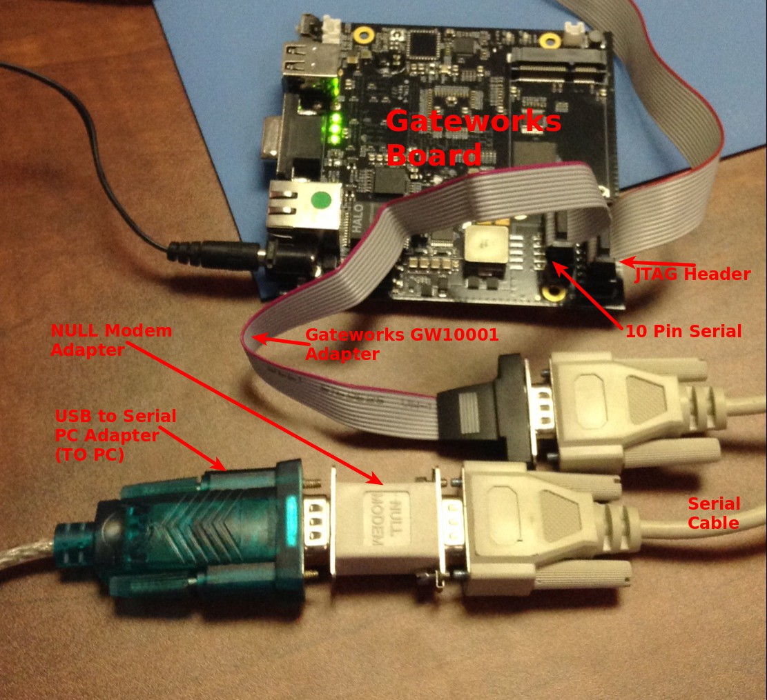
Example usage: RS232 connection to a PC
- Connect all hardware / cables
Note: A NULL MODEM adapter / cable may need to be used between the Gateworks board and a PC!

- The serial port must be configured on the Gateworks board using the stty command for the baud rate:
# stty --help
BusyBox v1.19.4 (2013-06-26 04:34:22 PDT) multi-call binary.

Usage: stty [-a|g] [-F DEVICE] [SETTING]...

Without arguments, prints baud rate, line discipline,
and deviations from stty sane

        -F DEVICE       Open device instead of stdin
        -a              Print all current settings in human-readable form
        -g              Print in stty-readable form
        [SETTING]       See manpage
Set the baud rate, example shown below for 115200:
root@OpenWrt:/# stty -F /dev/ttyS1 115200
Also Verify Flow Control: (adjust below example to exact application)
stty -crtscts -F /dev/ttyS1
- Configure PC:
- On the receiving PC, a terminal program can be used. For example:
- Windows: putty, hyperterm
- Linux: screen, minicom
- Example (adjust as necessary)
screen /dev/ttyS1 115200,cs8
- Example (adjust as necessary)
- Be sure to select the same baud rate, format (ie 8 data bits, no parity, 1 stop bit - aka 8N1 or cs8) and flow control as configured on the Gateworks board.
- On the receiving PC, a terminal program can be used. For example:
- Test Connection:
- A quick way to test this is to use an echo statement from the console of the Gateworks board like so:
# echo "0" > /dev/ttyS1
- A quick way to test this is to use an echo statement from the console of the Gateworks board like so:
The character '0' should appear on the serial console on the PC.
Troubleshooting:
- make sure you are either not using hardware/software flow control, or in the case that you do have hardware flow control (CTS/RTS or DTR/DSR) they are properly connected.See Link Here
- use a null-modem if needed (DTE vs DCE)
- make sure both ends are RS232 compliant (as opposed to TTL level logic)
RS485
Some Gateworks boards have RS485 transceivers connected to host CPU UART's. This often is an optional feature that must be loaded at the factory. Please contact support@… via email for more information.
RS485 uses a differential pair and is typically half-duplex such that the TX and RX share a differential pair on a multi-master bus and the TX and an enable that is controlled via one of:
- always enabled (only useful if there is only a single transmitter on the bus)
- connected to UART RTS line
- connected to host CPU GPIO
Because of the half-duplex nature, typically custom software needs to be written to:
- control the enabling of the transmit driver (sometimes this is done for you in the driver)
- receive the data you sent directly after sending (unless the driver does this for you)
- implement a protocol such that multiple masters know when it is there turn to transmit
In a typical scenario you may have two devices on an RS485 half-duplex bus, NodeA and NodeB and a conversation would look like this:
- NodeA enables its transmitter, sends out a request packet, then disables its transmitter and waits for a response
- NodeB waits for a request packet and until it sees one its transmitter is not enabled. When it receives the request it enables its transmitter, sends a response, then disables its transmitter.
- NodeA knows the exact nature of the response so it can wait until the message is complete then knows that it can transmit again
The following table and sections below provides per-board details of RS485:
| Family | Board | TXEN | Transceiver | Termination | Fail-Safe Bias | Notes |
|---|---|---|---|---|---|---|
| Newport | GW630x / GW640x | gpio12 | SP335E | optional (gpio16) | included | |
| Ventana | GW52xx (optional) | gpio193 | MAX14840 | optional | optional | TIOCSRS485 support |
| GW53xx (optional) | gpio193 | MAX14840 | optional | optional | TIOCSRS485 support | |
| GW54xx (optional) | gpio193 | MAX14840 | optional | optional | TIOCSRS485 support | |
| GW551x+GW16111 | gpio19 | MAX14840 | optional | 4.75k pull up/down | see ventana RS485 below | |
| Laguna | GW238x+GW16067 | gpio3 | MAX3485 | optional | 4.75k pull up/down | use tcdrain() and userspace /sys/class/gpio/gpio3 |
| Rincon | GW2361 (optional) | RTS | MAX3485 | off-board | off-board | use tcdrain() and TIOCMBIC/TIOCMBIS ioctl |
| Cambria | GW235x (optional) | DTR | MAX3485 | optional | optional | use tcdrain() and TIOCMBIC/TIOCMBIS ioctl |
Note that if a driver supports TIOCSRS485 (in other words it handles the assertion/de-assertion of TXEN in the driver) this is preferred over using tcdrain() to determine when the FIFO is empty as tcdrain() can have considerable latency at small transmit sizes.
References:
- TI RS-485 Design Guide - excellent source of info regarding termination, multi-master transmission, line length etc
- https://en.wikipedia.org/wiki/RS-485
RS485 Termination
As a general rule, termination resistors should be placed at both far ends of the RS485 network. Without termination resistors reflections of fast driver edges can cause data corruption. Termination resistors also reduce electrical noise sensitivity due to lower impedance. The value of each termination resistor should be equal to the cable characteristic impedance (typically 120 ohms for twisted pairs).
Some boards with RS485 capability may have transceivers with specific fail-safe features within the transceiver however optional on-board termination resistors typically exist as well and it is the responsibility of the system designer to determine where termination needs to go and what values should be used. In general, gateworks boards with RS485 transceivers have an optional resistor for termination that can be loaded with a customer specified value. Contact sales@… via e-mail for more information.
References:
- Maxium Tutorial 763 - Guidelines for Proper Wiring of an RS-485 Network
- https://en.wikipedia.org/wiki/RS-485
RS485 Failsafe Bias Resistors
When inputs are between -200mV and +200mV the receiver output is 'undefined'. There are four common fault conditions that result in this undefined receiver output that can cause erroneous data:
- All transmitters in a system are not driving
- The receiver is not connected to the cable
- The cable has an open
- The cable has a short
Fail-safe biasing is used to keep the receiver's output in a defined state when one of these conditions occur. The biasing consists of a pull-up resistor on the noninverting line and a pull-down resistor on the inverting line. With proper biasing, the receiver will output a valid high when any one of the fault conditions occur. These fail-safe bias resistors should be placed at the receiver end of the transmission line.
Some boards with RS485 capability may have on-board termination resistor options and it is the responsibility of the system designer to determine where termination needs to go and what values should be used. In general, gateworks boards with RS485 transceivers have an optional resistor for termination that can be loaded with a customer specified value. Contact sales@… via e-mail for more information.
on-board failsafe bias resistors 4.75Kohm pulls and an optional on-board 121ohm load termination resistor.
References:
- Maxium Tutorial 763 - Guidelines for Proper Wiring of an RS-485 Network
- https://en.wikipedia.org/wiki/RS-485
Cambria
The Cambria GW2350 and GW2358 optionally supports half-duplex, multi-drop RS485:
- TL16C752B UART
- MAX3485 transceiver
- TXEN connected to DTR
- optional on-board termination resistor
- optional on-board fail-safe bias resistors
By 'optional' this means the baseboard design supports this, but it is not loaded on standard product therefore would be a Gateworks Special. Contact sales@… if interested to see if a configuration already exists.
Your software must assert/de-assert DTR manually (see #rs485-example example code) or the uart driver would need to be modified to add TIOCSRS485 ioctl support.
Rincon
The Rincon GW2361 supports half-duplex, multi-drop RS485:
- DM6446 (CPU) UART2 (/dev/ttyS2)
- MAX3485 transceiver
- TXEN connected to RTS
Your software must assert/de-assert RTS manually (see #rs485-example example code) or the uart driver would need to be modified to add TIOCSRS485 ioctl support.
Laguna
The GW16067 IO Expansion module for the GW2380/2/3 supports half-duplex, multi-drop RS485:
- CNS3xxx UART2 (/dev/ttyS2)
- MAX3485 transceiver
- TXEN connected to gpio3
- optional on-board termination resistor (R5)
- on-board fail-safe bias resistors (R3/R7) by default are 4.75k pull-up on D+, 4.75k pull-down on D- (bus defaults to logic 1 - never idle)
By 'optional' this means the baseboard design supports this, but it is not loaded on standard product therefore would be a Gateworks Special. Contact sales@… if interested to see if a configuration already exists.
Your software must assert/de-assert gpio3 manually (see #rs485-example example code) or the uart driver would need to be modified to add TIOCSRS485 ioctl support.
Ventana
The GW52xx/GW53xx/GW54xx support optional half-duplex, multi-drop RS485:
- IMX6 UART1 (/dev/ttymxc0)
- MAX14840 transceiver
- TXEN connected to gpio193
- optional on-board termination resistor
- optional on-board fail-safe resistors (D+ pull-up and D- pull-down)
By 'optional' this means the baseboard design supports this, but it is not loaded on standard product therefore would be a Gateworks Special. Contact sales@… if interested to see if a configuration already exists.
Your software must use the TIOCSRS485 ioctl to configure TXEN (see #rs485-example example code).
The GW551x + GW16111 breakout module support half-duplex, multi-drop RS485:
- IMX6 UART2 (/dev/ttymxc1)
- Note that a jumper must be placed on J10:2-3 to enable RS485 RX (routes UART2 RX to RS485 vs RS232 transceiver)
- Note that a jumper must be placed on J10:1-2 to enable RS232 (routes UART2 to RS232 transceiver)
- MAX14840 transceiver
- TXEN connected to gpio19, or always enabled, or enable on transmit (selected via J10 jumper)
- always drive mode - jumpers placed on J10:2-3 and J10:4-5 will cause the transceiver to always have its transmit enabled. This is useful for fast signal switching (fast/large bus) if you are using a single master and one or more receivers.
- TXD drive mode - jumpers placed on J10:2-3 and J10:7-8 will cause the transceiver to be enabled only when TX is asserted. Because there are 4.75k pull's on D+/D- the bus is never 'idle'. This is useful for multi-master scenarios but could pose issues with fast/large busses if the 4.75pull's are not strong enough to switch the signals quick enough.
- DIO-drive mode - jumpers placed on J10:2-3 and J10:7-8 will cause the transceiver to be enabled only when IMX_DIO1 (gpio19) is asserted high. This is useful for fast/large busses where the TXD drive mode doesn't provide fast enough switching. If using this mode you either need to manage the assertion/de-assertion of gpio19 in usersapce or modify the GW551x device-tree to configure rs485-txen for TIOCSRS485 support by adding fsl,rs485-gpio-txen = <&gpio1 19 GPIO_ACTIVE_HIGH>; to the uart2 device-tree node in arch/arm/boot/dts/imx6qdl-gw551x.dtsi
- 121ohm termination (R38) is loaded and can be enabled by placing a jumper on J10:9-10
- 4.75k pull-up on D+, 4.75k pull-down on D- fail-safe bias resistors are loaded (R37/R40) (bus defaults to logic 1 - never idle)
Newport
The GW630x / GW640x have 2 CN80XX UART's (UART2/UART3: /dev/ttyAMA2 and /dev/ttyAMA3) going to a SP335E transceiver which allows selecting a variety of RS232/RS485 configurations:
- 2x RS232 w/o flow control
- 1x RS232 w/ flow control
- 1x RS485 half duplex
- 1x RS485 full duplex
RS485 modes feature:
- optional half-duplex, multi-drop RS585:
- CN80XX UART2 (/dev/ttyAMA2)
- optional on-board termination (enabled by gpio16)
- in-chip fail-safe protection to default idle inputs to logic-high (no external bias resistors required)
- TXEN connected to gpio12
The pl011 Linux driver supporting the CN80XX serial ports (SERIAL_AMBA_PL011 drivers/tty/serial/amba-pl011.c) does not look like it supports RS485 directly. While this support could be added you can alternatively drive the TXEN gpio12 directly in a user application for RS485 half-duplex.
Example Application
Here is an example application that uses the TIOCSRS485 ioctl to configure RS485 for drivers that directly control the transmit enable:
#include <ctype.h>
#include <errno.h>
#include <stdlib.h>
#include <stdio.h>
#include <string.h>
#include <termios.h>
#include <time.h>
#include <unistd.h>
#include <fcntl.h>
#include <sys/ioctl.h>
#include <linux/serial.h>

#ifndef TIOCSRS485
#define TIOCSRS485        0x542F
#endif

/** main function
 */
int main(int argc, char** argv)
{
        struct termios orig_ttystate, ttystate;
        int fd, sz, rz, bytes;
        speed_t speed;
        const char *baud, *mode, *dev;
        int timeout = 2; // time in seconds to wait for response
        char *msg = NULL;
        char buf[8192];
        time_t start;

        if (argc < 4) {
                fprintf(stderr,
                        "usage: %s <device> <baud> <mode> [<message>]\n",
                        argv[0]);
                exit(1);
        }

        dev = argv[1];
        baud = argv[2];
        mode = argv[3];
        if (argc > 4)
                msg = argv[4];

        // open device
        fd = open(dev, O_RDWR | O_NONBLOCK | O_NOCTTY);
        if (fd <= 0) {
                perror("open");
                exit(-1);
        }

        // get original ttystate
        tcgetattr(fd, &orig_ttystate);

        // create a sane TTY state (raw mode, no HW/SF flow control)
        memset(&ttystate, 0, sizeof(ttystate));

        // enable receiver and ignore modem status lines
        ttystate.c_cflag |= CREAD;
        ttystate.c_cflag |= CLOCAL;

        // data-size
        ttystate.c_cflag &= ~CSIZE;
        switch(mode[0]) {
        case '5': ttystate.c_cflag |= CS5; break;
        case '6': ttystate.c_cflag |= CS6; break;
        case '7': ttystate.c_cflag |= CS7; break;
        case '8': ttystate.c_cflag |= CS8; break;
        default: fprintf(stderr, "invaid character size in %s\n", mode); break;
        }

        // parity
        ttystate.c_cflag &= ~PARODD;
        ttystate.c_cflag &= ~PARENB;
        switch(toupper(mode[1])) {
        case 'N': break; // no parity
        case 'O': ttystate.c_cflag |= (PARENB | PARODD); break; // odd
        case 'E': ttystate.c_cflag |= PARENB; break; // even
        default: fprintf(stderr, "invaid parity in %s\n", mode); break;
        }

        // stop bits
        switch(toupper(mode[2])) {
        case '1': ttystate.c_cflag &= ~CSTOPB; break;
        case '2': ttystate.c_cflag |= CSTOPB; break;
        default: fprintf(stderr, "invaid stop bit mode in %s\n", mode); break;
        }

        // baudrate
        switch(atoi(baud)) {
        case 1200: speed = B1200; break;
        case 2400: speed = B2400; break;
        case 9600: speed = B9600; break;
        case 19200: speed = B19200; break;
        case 38400: speed = B38400; break;
        case 57600: speed = B57600; break;
        case 115200: speed = B115200; break;
        case 230400: speed = B230400; break;
        case 460800: speed = B460800; break;
        default: fprintf(stderr, "invalid baud rate %s\n", baud); break;
        }
        if (cfsetispeed(&ttystate, speed))
                perror("cfsetispeed");
        if (cfsetospeed(&ttystate, speed))
                perror("cfsetospeed");

        // set tty state
        printf("setting ttystate\n");
        if (tcsetattr(fd, TCSANOW, &ttystate))
                perror("tcsetattr");

        // configure rs485
        {
                struct serial_rs485 rs485;

                printf("enabling rs485 via TIOCSRS485\n");
                memset(&rs485, 0, sizeof(rs485));
                rs485.flags = SER_RS485_ENABLED | SER_RS485_RTS_ON_SEND;
                if (ioctl(fd, TIOCSRS485, &rs485))
                        perror("TIOCSRS485");
        }

        // flush in/out data
        tcflush(fd, TCIOFLUSH);

        // transmit data
        if (msg) {
                printf("sending...\n");
                if (strcmp("STDIN", msg) == 0) {
                        while (1) {
                                sz = read(0, buf, sizeof(buf));
                                printf("transmitting %d bytes...\n", sz);
                                if (write(fd, buf, sz) != sz) {
                                        perror("tx");
                                        break;
                                }
                        }
                } else {
                        sz = strlen(msg) + 1;
                        printf("transmitting %d bytes...\n", sz);
                        if (write(fd, msg, sz) != sz)
                                perror("tx");
                }
        }

        // receive data
        printf("reading...\n");
        while (1) {
                memset(buf, 0, sizeof(buf));
                rz = read(fd, buf, sizeof(buf) - 1);
                if (rz < 0) {
                        perror("read failed");
                        break;
                }
                if (rz == 0)
                        continue;
                printf("rx %d(%d): '%s'\n", rz, strlen(buf), buf);
        }

        // restore terminal state
        tcsetattr(fd, TCSANOW, &orig_ttystate);

        close(fd);

        return 0;
}
Ventana boards with on-board RS485 use ARM gpio193 as the TXEN and our Ventana BSP's support the TIOCSRS485 ioctl such that you do not need to manage the transmitter enable other than enable it and set its polarity when you configure the serial port:
struct serial_rs485 rs485;

memset(&rs485, 0, sizeof(rs485));
rs485.flags = SER_RS485_ENABLED | SER_RS485_RTS_ON_SEND;
if (ioctl(fd, TIOCSRS485, &rs485))
  perror("TIOCSRS485");
If a board connects RTS, DTR, or a gpio to TX-Enable but does not support the TIOCSRS485 you can alter your code to enable/disable the TX-Enable as needed.
For example the following function:
/** write_file - write to a file
 * @param str to write
 * @param fname to write to
 *
 * This is used to set/configure GPIO's via the sysfs interface to gpio class
 */
int write_file(const char* str, const char* fname)
{
        FILE *file;
        int ret = -EIO;

        file = fopen(fname, "w");
        if (file) {
                ret = fprintf(file, "%s\n", str);
                if (ret <= 0)
                        ret = -EIO;
                fclose(file);
                return 0;
        }
        return ret;
}


/** assert_tx - enable/disable TX on a device
 * @param dev - serial device
 * @param enable - enable or disable
 * @returns 0 on success otherwise error
 */
int assert_tx(int fd, const char *txen, unsigned char enable)
{
        char str[64];
        int t;

        if (!txen)
                return 0;

        printf("%sasserting %s\n", (enable)?"":"de-", txen);
        if (strcasecmp(txen, "DTR") == 0) {
                // assert DTR on enable, de-assert on disable
                t = TIOCM_DTR;
                return ioctl(fd, (enable)?TIOCMBIC:TIOCMBIS, &t);
        } else if (strcasecmp(txen, "RTS") == 0) {
                // assert RTS on enable, de-assert on disable
                t = TIOCM_RTS;
                return ioctl(fd, (enable)?TIOCMBIC:TIOCMBIS, &t);
        } else if (strncasecmp(txen, "gpio", 4) == 0) {
                t = atoi(txen + 4);
                sprintf(str, "/sys/class/gpio/gpio%d/value", t);
                write_file((enable)?"1":"0", str);
        }

        return 0;
}

int main(int argc, char **argv) {
        ...

        // txen is a string: DTR, RTS, or gpio<n>
        if (txen && (0 == strncasecmp(txen, "gpio", 4)))
        {
                char str[64];
                int gpio = atoi(txen + 4);

                printf("exporting gpio%d\n", gpio);
                sprintf(str, "%d", gpio);
                write_file(str, "/sys/class/gpio/export");
                sprintf(str, "/sys/class/gpio/gpio%d/direction", gpio);
                write_file("out", str);
                sprintf(str, "/sys/class/gpio/gpio%d/value", gpio);
                write_file("0", str); // assuming TXEN active-high
        }

        // transmit data
        assert_tx(fd, txen, 1); // assert TXEN
        write(fd, buf, sz); // transmit data
        tcdrain(fd); //wait for all characters to be transmitted
        assert_tx(fd, txen, 0); // de-assert TXEN

        // receive data
        ...
Specific Product / Model Notes
Newport
Most Newport products have a flexible MaxLinear SP335E RS-232/RS-485/RS-422 transceiver which is software configurable. For these boards the Bootloader hwconfig environment variable can be used to configure the functionality of the serial ports at power-up between dual RS232 without flow control (default), single RS232 with hardware flow control, and RS485 (full/half duplex and optional termination). See Newport bootloader hwconfig for more details.
If you wish to configure the SP335E transceiver yourself you can control it at runtime through the following GPIO's (which is what the Boot firmware will do for you via the hwconfig variable):
- GPIO21: UART_HALF - selects full (low) or half (high) duplex (RS485 mode only)
- GPIO22: UART_TERM - disables (low) or enables (high) on-chip termination (RS485 mode only)
- GPIO23: UART_RS485 - selects between RS232 (low) and RS245 (high) modes
See gpio for details on using GPIO from Linux userspace or use the U-Boot bootloader gpio command.
The CN80XX / CN81XX has 4 TTL level UARTs with the following mapping:
| UART | device-tree alias | Linux device |
|---|---|---|
| UART0 | serial0 | /dev/ttyAMA0 |
| UART1 | serial1 | /dev/ttyAMA1 |
| UART2 | serial2 | /dev/ttyAMA2 |
| UART3 | serial3 | /dev/ttyAMA3 |
The Linux kernel uses the console parameter from the Kernel cmdline to specify the serial console. You can usually modify the 'console' U-boot env variable if you want to change the default console UART as it typically gets passed on to the kernel:
Newport > setenv console '/dev/ttyAMA2,115200n8'; saveenv
- Specify that Linux and userspace use UART2
The U-Boot Bootloader (as well as kernel if the console cmdline is not specified) uses the device-tree 'chosen' node 'stdout-path' property to specify serial console. For example the default is specified in the cn81xx-linux.dtsi:
        chosen {
               stdout-path = "serial0:115200n8";
        };
If you wish to change the serial console in the BDK or ATF, you will need to modify the source code which will take some digging.
Laguna: GW2382
J8 is an expansion header and is by default mapped to /dev/ttyS2. J2 and J4 are connected to /dev/ttyS0. The GPS is hooked to /dev/ttyS1.
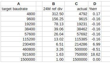
Laguna: Baud Rate
The Laguna Family has the option of 2 clocks for the serial port, 24MHz and 14.7456MHz.
By default the 24MHz clock is loaded. This clock creates drift for some baud rates as seen below.
Because this drift is consistent on Laguna boards, Laguna to Laguna serial will work at all baud rates.
Therefore, we suggest using rates below 115200. Please contact support at Gateworks if higher baud rates are required.

Attachments (2)
- baudrates.jpg (34.9 KB ) - added by 6 years ago.
- serial2391.jpg (270.5 KB ) - added by 6 years ago.
Download all attachments as: .zip