
| Version 5 (modified by , 11 months ago) ( diff ) |
|---|
Venice GW7905
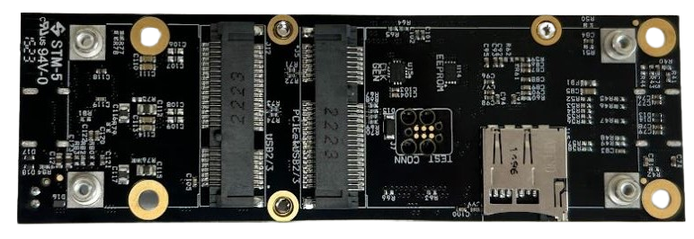
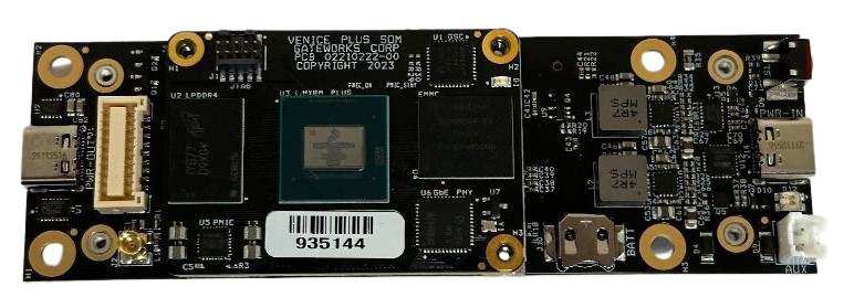
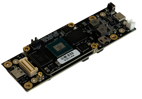
The Venice GW7905 is a small single board computer that features a half-card Mini-PCIe slot, a full size Mini-PCIe slot, and USB. The GW7905 can be used with a GW7020 SOM that features the NXP i.MX8M Plus Quad Core processor running at 1.6GHz, 1GB DRAM, 8GB of Flash.
Features

- NXP i.MX8M Plus Quadcore 1.6GHz SoC
- 1GB LPDDR4 memory, 8GB eMMC Flash
- Gateworks System Controller (GSC) with integrated EEPROM, button controller, and ADC's
- GPS
- microSD
- I/O connector with I2C, SPI, GPIO
- 1x full-length miniPCIe socket with PCI/USB3 (via mux) and USB2.0
- 1x half-length miniPCIe socket with USB2.0 and USB3.0
- USB Type-C with USB PD Sink capability and peripheral support
- USB Type-C with USB 3.0 host support
- Wide range buck/boost DC supply (3.6V to 20V)
Getting Started
The GW7905 can be powered using the J13 (2-pin) connector (supports 3.6 to 20V DC input) or through the J14 USB Type-C connector using a USB-C charger. The USB-C power profile supports the following profiles by default:
- PDO1 (low priority) 5V@1.5A
- PDO2 (medium) 15V@1.5A
- PDO3 (high priority) 20V@1.0A
Other profiles can be programmed into the controller as well. Contact support for other options.
Depending on the type of cards loaded in the Mini-PCIe sites PD02 or PD03 profiles might be required. The board typically runs at 2.5W without any Mini-PCIe cards installed.
To get to the serial console, please use the standard Getting Started Wiki
Software
Please use the standard Venice software practices for this SBC, with a note that by default it ships with the i.MX8M Plus SOM. This means all image file names will have the 'p' in the name, indicating the 'plus'
Read more about software here: venice
Connectors
See the following sections for details on the board connectors and pinouts.


J13 Power
A 2MM pitch power header that supports 3.6 to 20V DC input. The 2-pin connector is at location J15 in a 1x2x2mm configuration. The mating connector is PAP-02V-S, available from Digikey as part number 455-1486-ND.. Pin 1 is power, and Pin 2 is ground.
J5 Mini-PCIe Full Length
Supports PCIe and USB 3.0 (controlled by mux), USB 2.0, PERST#, WDIS#
J12 Mini-PCIe Half Length
Supports PCIe and USB 2.0, PERST#, WDIS#
J14 USB
This is a USB TYPE-C that can support USB 3.0 peripheral and power delivery to the board.
J1 USB
This is a USB TYPE-C that can support USB 3.0 host and power output from the board.
J15 MicroSD
A microSD socket with ESD protection
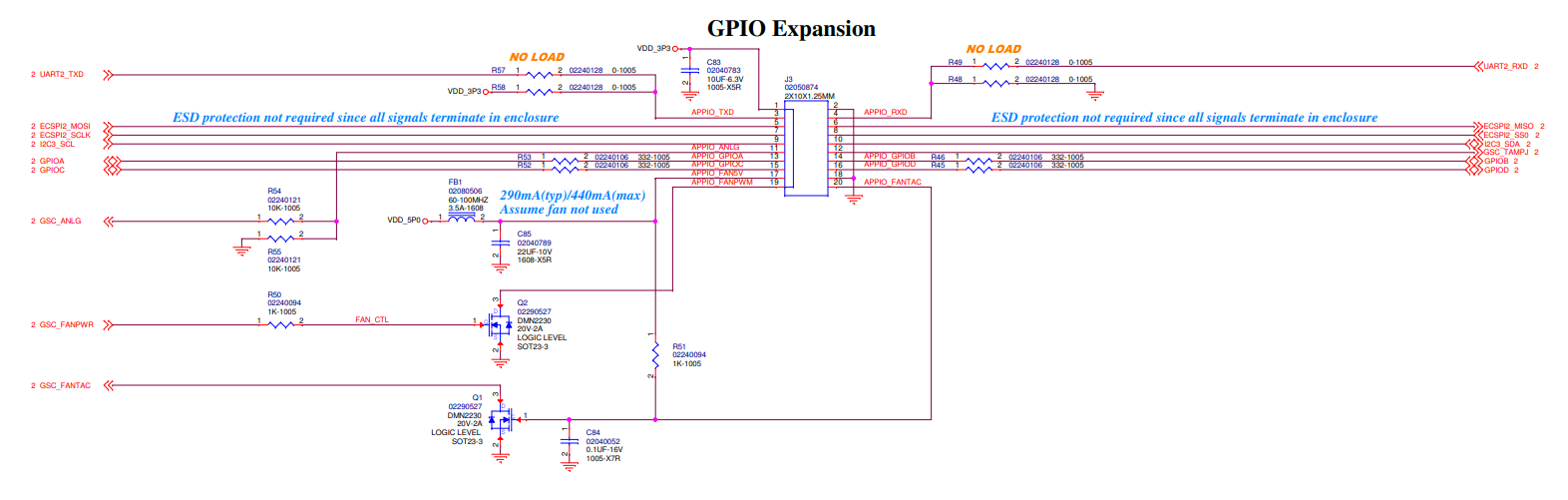
J3 GPIO Expansion
A 2x10 connector (20 pins total) that supports a variety of signals as defined in the screenshot below.
The connector is a 20-pin header in a 2x10 configuration with 1.25mm pin spacing. The mating connector is a JST GHDR-20V-S, available from Digi-Key as part number 455-1913-ND. The mating connector pins are JST SGHD-002GA-P0.2, available from Digi-Key as part number 455-1914-2-ND. The digital I/O signals include signal conditioning in the form of a series 332 ohm resistor.
A dev kit cable is the GW10127: https://shop.gateworks.com/index.php?route=product/product&product_id=214&search=20

J2 GPS Antenna
The GW7905 uses the ZOE-M8Q GPS.
More information about the GPS and antenna can be found on the GPS Wiki Page
Resources
This wiki page is specific to the GW7905. For general information, please use the rest of this wiki:
- Wiki Home - For WiFi, Cellular, GPIO, UART, DIO, etc etc
- Venice Wiki - Overall, the GW7905 belongs to the Venice family of SBCs
- Gateworks Support
Attachments (5)
- 7905j3.png (94.5 KB ) - added by 11 months ago.
- GW7905bot.png (304.1 KB ) - added by 11 months ago.
- GW7905top.png (310.8 KB ) - added by 11 months ago.
- GW7905topangle.png (204.3 KB ) - added by 11 months ago.
- halfcard.PNG (222.5 KB ) - added by 11 months ago.
Download all attachments as: .zip