
| Version 12 (modified by , 6 years ago) ( diff ) |
|---|
Ventana LVDS Support
Gateworks LCD Development Kits
Gateworks offers packaged LCD touchscreens that are plug and play with the Ventana board that have a LVDS interface.
Gateworks offers a 7" and 8" display. Use the following part numbers for ordering:
- 7" WSVGA (1024x600) display with backlight and 5pt capacitive touch:
- GW17029 7" LCD Display
- GW10109 (8in) GW16113 (36in) GW16114 (60in) Cable
- GW16114-1 Touch Interface (for 7" LCD)
- GW10111 Aluminum Bezel (for 7" LCD)
- 8" XGA (1024x768) display with backlight and 5pt capacitive touch:
- Special Order - 250 piece minimum
- GW17030 8" LCD Display
- GW10109 (8in) GW16113 (36in) GW16114 (60in) Cable
- GW16114-2 Touch Interface (for 8" LCD)
Ventana LVDS Connector Specifications
The Ventana GW5400/GW5300/GW5200 designs all support LVDS via a 30 pin connector that provides:
- 3D+C (3 differential pairs data, 1 differential pair clock at 2.5V) for LVDS Video in compliance iwth EIA-644
- Signalling is 1.0V to 1.4V (1.2V common mode) with a 400mV swing (3.3V logic level)
- the maximum pixel clock (85MHz) and the maximum clock of the LVDS serializer results in a maximum resolution of WXGA (1366x768@60Hz with 35% blanking)
- 3D+C allows for 6bit-per-color for 18bit color (262K colors) for 6bit per color
- displays which support 4D+C for 6bit-per-color (24bit color) typically use the 4th data pair for bit7/bit8 thus can likely be interfaced with Ventana as 6bit 3D+C (consult display datasheets)
- 1xPWM (3.3V) For backlight brightness
- 1xGPIO (3.3V) For control
- 1xGPIO (3.3V) for touchscreen controller IRQ#
- 1xi2c (3.3V) for EDID and touchscreen or backlight controller
- 3.3VDC (always-on power)
- 5.0VDC (always-on power)
Refer to the individual product manuals for more details.
The LVDS video output is available through a 30-pin connector in a 1x30 configuration with 1mm pin spacing.
- The mating connector for a discrete wire plug is a Hirose DF19-30S-1C, available from Digi-Key as part number H3104-NDlink here.
- The crimp contacts for the discrete wire connector are Hirose DF19A-3032SCFA, available from Digi-Key as part number H12154CT-ND link here.
- Crimp Gun H3131-ND
IMX6 LVDS details:
- Display interface clock: 20-85 MHz
- Serializer clock: 140-595 MHz
- while the IMX6 itself has 2 LVDS ports each supporting up to 4D+C (4 data pairs plus 1 clock pair) which can be used as separate displays or combined (see IMX6DQRM section 39.4.2), the Ventana designs only bring out 3D+C (3 data pairs plus 1 clock pair) of the first lvds port
- for details on bitmapping supported see IMX6DQRM section 39.5.2
Ventana 30-pin LVDS connector pinout:
| Pin | Signal | Notes |
|---|---|---|
| 1 | BACK_EN# | GPIO1_IO10 (gpio10) |
| 2 | 3.3V | |
| 3 | 3.3V | |
| 4 | 3.3V | |
| 5 | BACK_ADJ | PWM4 or GPIO1_IO18 (gpio18) |
| 6 | SCL | I2C3 - /dev/i2c-2 |
| 7 | SDA | I2C3 - /dev/i2c-2 |
| 8 | TX0- | differential pair |
| 9 | TX0+ | differential pair |
| 10 | GND | |
| 11 | TX1- | differential pair |
| 12 | TX1+ | differential pair |
| 13 | GND | |
| 14 | TX2- | differential pair |
| 15 | TX2+ | differential pair |
| 16 | GND | |
| 17 | CLK- | differential pair |
| 18 | CLK+ | differential pair |
| 19 | GND | |
| 20 | 5V | |
| 21 | 5V | |
| 22 | GND | |
| 23 | GND | |
| 24 | 5V | |
| 25 | 5V | |
| 26 | 5V | |
| 27 | SCL | I2C3 - /dev/i2c-2 |
| 28 | SDA | I2C3 - /dev/i2c-2 |
| 29 | TOUCH_IRQ | IMX6 GPIO7_IO12 (gpio204) |
| 30 | N/C |
- The BACK_EN# signal is an ARM GPIO and can be routed to various LVDS display features. Typically this is either used as a RST# or a backlight enable.
- The BACK_ADJ signal can be an ARM GPIO or a PWM.
Note that the Ventana bootloader always configures BACK_EN# (gpio10) as output-low but leaves BACK_ADJ as a high-impediance input with a 100k pull-up unless the panel env is set to one of the supported LVDS configurations (see below) in which case the bootloader enable_lvds function drives BACK_EN# low making it appropriate if connected to an active low enable or active high reset and BACK_ADJ high making it 100% brightness.
Note that the Ventana Linux kernel does not configure BACK_EN# (gpio10) (thus leaving it configured from the bootloader and exportable/managable by userspace) but does configure BACK_ADJ as PWM4 adjustable via /sys/class/backlight.
If the above configuration is not compatible with your LVDS display you will need to make adjustments to the bootloader and/or kernel.
LVDS Power Pins
The LVDS connector that we use has three pins assigned to 3.3V and five pins assigned to 5V. The maximum current depends on the wire gauge of the cable used with the connector and the 5V supply on the board. A 36 gauge cable is 0.5A per contact, a 30 gauge cable is 0.9A per contact, and a 28 gauge cable is 1A per contact.
LVDS Connector 3.3V:
- The GW52xx, GW53x, and GW54xx all have 30W available from the 3.3V supply and you can subtract ~3W for baseboard operation and additional power depending on PCIe devices (ie radios) to determine what is left for LVDS.
- The limiting factor for the 3.3V current is going to be the connector and cable combination. Since 3.3V power has 3 pins, there is between 1.5A and 3A available depending on the wire gauge.
LVDS Connector 5V:
- 5V power supplies on the Ventana products have a much lower current rating than the 3.3V supply therefore you should pay careful attention to the 5V power needs of your display.
- GW52xx has a 1A capable 5V supply shared between CAN transceiver, HDMI DDC, and LVDS.
- GW53xx-B and earlier board revisions have a 800mA capable 5V supply shared between front-panel USB, CAN transceiver, HDMI DDC, and LVDS.
- GW53xx-C, D, and E board revisions have a 1.6A capable 5V supply shared between front-panel USB, CAN transceiver, HDMI DDC, and LVDS.
- Note - The 3.3V to 5V boost part used on these revisions has an inrush limitation of 100mA at power-up, causing some displays to not reliably power on
- GW53xx-F and above have a 700mA capable 5V supply shared between CAN transceiver, HDMI DDC, and LVDS.
- GW54xx has a 600mA capable 5V supply shared between CAN transceiver, HDMI DDC, FAN power, and LVDS.
Touchscreen sensors
Touchscreen's are displays that have bonded to them a thin glass sensor to detect touch events. These can have a variety of features and technologies:
- resistive touch vs capacitive (each has their pro's and con's)
- communication channels (I2C vs USB typically) - the Ventana LVDS connector itself supports an i2c channel although USB can be picked up from the main-board on different connectors
- multi-touch vs single-touch
- other features...
There is a large variety of touch sensor controllers (the chip) and touch sensor's (the glass with the micro-wires or elements that connect to the controller chip). Each controller chip has a certain number of sensor circuits that can limit the size of the display.
The panels that we offer 'out-of-the-box' support for listed below use one of the following controller chips:
- eGalax (used on the Freescale MCIMX-LVDS1 10" XGA Touchscreen Display)
- FocalTech FT5x06 (used on the DLC700JMGT4 7" WSVGA Touchscreen Display)
- Goodix GT9110 (used on the DLC800FIGT3 8" XGA Touchscreen Display)
Software Support and Configuration
Gateworks U-Boot Bootloader:
- supports 'display' (not touch) of the various displays below
- very easy to add additional support to
gw_ventana.cby knowing the display timings - the
panelenv variable enables display output maching one of the device names in the displays array- un-setting
panelwill auto-detect displays that have that capability (typically i2c probing the touch controller) - setting
panelto none disables display out completely
- un-setting
- the
displayenv variable will select the 'native-mode' device-tree node for the LCD display to timings for the kernel (supported in the 3.10.53 vendor kernel used on the Android Kitkat BSP, Yocto v1.8 BSP, and the latest OpenWrt (see: https://github.com/Gateworks/openwrt))
Freescale Linux Kernels (3.0.35, 3.10.17, 3.10.31, 3.10.53, 3.14.28, 3.14.48):
- the video kernel parameter can specify display details for mxcfb0, mxcfb1, mxcfb2, mxcfb3 devices (IMX6Q can support 4 simultaneous display out, while IMX6DL can support 2).
- see here for details
- For 3.10.31 and later kernels the video mode settings describing resolution and timings are selected through device-tree properties
- For earlier kernels the video mode settings are selected by specifying one of the following in the mxcfb device descriptor in the video command line parameter
Linux Display Driver Support:
- The Gateworks Yocto and Android BSP's support A driver supporting the i.MX6 IPU is required for display. This is available in the Gateworks 3.0.35 and 3.10.17 kernels available in our Yocto BSP
- mainline linux driver support is being worked on currently and targeted for the 3.15 kernel
- The touch controller on the EXC7200 is compatible with the 'egalax_ts' linux driver
- The display requires either a panel driver or device-tree configuration depending on kernel
- The backlight can be controlled through the standard Linux pwm-backlight driver
Linux Touchscreen Driver Support:
- touchscreen's are typically I2C or USB based devices with drivers in the
drivers/input/touchscreendirectory
Troubleshooting Backlight Portion
In some cases the device tree node used by the linux pwm-backlight driver may need to be adjusted if
"flickering" exists (example). This phenomenon is caused by a pwm frequency setting that is too low for the connected display's backlight which creates a visual artifact that may be detectable by the human eye.
As described in the pwm device tree bindings documentation, the backlight node of the device tree has a property labelled pwms. This property has includes the pwm-specifier which typically encodes the chip-relative PWM number and the PWM
period in nanoseconds.
backlight {
	compatible = "pwm-backlight";
	pwms = <&pwm1 0 5000000>;		/* 1 / (5000000 / 1000000000) = 200 Hz */
	brightness-levels = <
		0  1  2  3  4  5  6  7  8  9
		10 11 12 13 14 15 16 17 18 19
		20 21 22 23 24 25 26 27 28 29
		30 31 32 33 34 35 36 37 38 39
		40 41 42 43 44 45 46 47 48 49
		50 51 52 53 54 55 56 57 58 59
		60 61 62 63 64 65 66 67 68 69
		70 71 72 73 74 75 76 77 78 79
		80 81 82 83 84 85 86 87 88 89
		90 91 92 93 94 95 96 97 98 99
		100
		>;
	default-brightness-level = <100>;
};
If you want to make an adjustment to this frequency, you can use the fixfdt script in the bootloader. For example, to change the backlight frequency to 10kHz you would run the following command from the bootloader:
# The third value of the pwms property is in nanoseconds so to convert to Hz:
# 1 / (100000 / 1000000000) = 10 kHz
setenv fixfdt "fdt addr ${fdt_addr}; fdt set /backlight pwms <0x3d 0 100000>"
Troubleshooting Touchscreen Portion
There is a command line tool called evtest that can be used to check for touch events.
An example is shown below:
root@ventana:~# evtest
No device specified, trying to scan all of /dev/input/event*
Available devices:
/dev/input/event0:      EP0810M09
/dev/input/event1:      gsc_input
/dev/input/event2:      mma845x_a
/dev/input/event3:      fxos8700_m
Select the device event number [0-3]: 0
Input driver version is 1.0.1
Input device ID: bus 0x18 vendor 0x0 product 0x0 version 0x0
Input device name: "EP0810M09"
Supported events:
  Event type 0 (EV_SYN)
  Event type 1 (EV_KEY)
    Event code 330 (BTN_TOUCH)
  Event type 3 (EV_ABS)
    Event code 0 (ABS_X)
      Value    863
      Min        0
      Max     1023
    Event code 1 (ABS_Y)
      Value  -3374
      Min        0
      Max      599
    Event code 47 (ABS_MT_SLOT)
      Value      3
      Min        0
      Max        4
    Event code 53 (ABS_MT_POSITION_X)
      Value      0
      Min        0
      Max     1023
    Event code 54 (ABS_MT_POSITION_Y)
      Value      0
      Min        0
      Max      599
    Event code 57 (ABS_MT_TRACKING_ID)
      Value      0
      Min        0
      Max    65535
Properties:
Testing ... (interrupt to exit)
Event: time 1430493672.054573, type 3 (EV_ABS), code 47 (ABS_MT_SLOT), value 0
Event: time 1430493672.054573, type 3 (EV_ABS), code 53 (ABS_MT_POSITION_X), value 63
Event: time 1430493672.054573, type 3 (EV_ABS), code 54 (ABS_MT_POSITION_Y), value 128
Event: time 1430493672.054573, type 3 (EV_ABS), code 0 (ABS_X), value 63
Event: time 1430493672.054573, type 3 (EV_ABS), code 1 (ABS_Y), value 128
Event: time 1430493672.054573, -------------- EV_SYN ------------
Event: time 1430493672.129208, type 3 (EV_ABS), code 57 (ABS_MT_TRACKING_ID), value -1
It is important verify the touchscreen is detected by running the following command in the example example:
root@ventana:/ # cat /proc/bus/input/devices
I: Bus=0018 Vendor=0416 Product=1001 Version=28bb
N: Name="Goodix Capacitive TouchScreen"
P: Phys=input/ts
S: Sysfs=/devices/soc0/soc.1/2100000.aips-bus/21a8000.i2c/i2c-2/2-0014/input/input0
U: Uniq=
H: Handlers=mouse0 event0
B: PROP=2
B: EV=b
B: KEY=400 0 0 0 0 0 0 0 0 0 0
B: ABS=2658000 3
Interrupts
You can see if interrupts are being sent to the touchscreen controller.
Run the command:
cat /proc/interrupts
Find the touch controller in the list.
Note the number of interrupts it currently has.
Then touch the screen a few times.
Then check the interrupts again to verify if it has increased.
Android Touchscreen
In addition to the above information, here is some more information that may be relevant to Android.
To detect touch events on Android, where evtest may not exist, try using the getevent command.
Example shown below, adjust command as necessary.
Note that values should appear on the serial console when the screen is touched.
This verifies the touchscreen is getting events.
root@ventana:/ # getevent /dev/input/event0
0003 0039 00000022
0003 0036 00000251
0003 0035 0000033b
0003 0030 0000003e
0003 0032 0000003e
0001 014a 00000001
0003 0000 0000033b
0003 0001 00000251
0000 0000 00000000
0003 0030 00000038
0003 0032 00000038
0000 0000 00000000
0003 0039 ffffffff
0001 014a 00000000
0000 0000 00000000
Supported Displays
While you should be able to make a wide variety of LVDS displays work, Gateworks provides software support and cables for several readily available displays. Please contact sales@… for details.
GW17047 DLC0700XDP21LF 7" WSVGA Touchscreen Display - Recommended
CollapsibleStart(Expand Details) The GW17047 DLC0700XDP21LF 7" WSVGA Touchscreen Display is a low-cost display supporting:
- 7" LCD 1024x600 display with backlight
- Physical size (W/H/D): 165.75 x 105.39 x 5.39mm
- Active area: 153.6 x 90.00mm
- Resolution: 1024x600 24bit RGB
- Pixel pitch: 0.05 x 0.15mm
- Pixel config: RGB stripes
- Mode: Transmissive, normally black
- Brightness: 200 nits
- Contrast: 700:1
- Backlight: LED
- Interface: LVDS
- Technology: IPS TFT
- Power consuption: 1W to 2W (typ)
- operating temperature: -20C to +70C
- 5pt Capacitive touch via FT5406 touch controller
- 10-point capacitive touch
- scanning frequency: >100 Hz
- channels: 28 (drive) * 16 (induction)
- active area: up to 8.9"
- transmission: i2c i2c-2@0x38
- operating temperature: -40C to +85C
- SmarterGlass LVDS-7 adapter board provides pwm-controlled backlight
- DLC0700XDP21LF-C-1 Datasheet
Gateworks Bootloader support:
- you can enable display out in the bootloader via:
setenv panel DLC0700XDP21LF
saveenv
Android Kitkat+ support:
- Enable display and touch support for Android KitKat by setting the
displayenv variable in the bootloader:setenv display DLC0700XDP21LF saveenv
Yocto Support:
- For the touch controller, use a fixfdt variable in the bootloader to invert the touch controller:
setenv display DLC700JMGT4
setenv fixfdt "${fixfdt}; fdt resize; fdt rm /soc/aips-bus@02100000/i2c@021a8000/edt-ft5x06@38 invert"
saveenv
GW17029 DLC700JMGT4 7" WSVGA Touchscreen Display - End of Life
This display is no longer carried by Gateworks. CollapsibleStart(Expand Details) The GW17029 DLC700JMGT4 7" WSVGA Touchscreen Display is a low-cost display supporting:
- 7" LCD 1024x600 display with backlight
- Physical size (W/H/D): 165.75 x 105.39 x 5.39mm
- Active area: 153.6 x 90.00mm
- Resolution: 1024x600 24bit RGB
- Pixel pitch: 0.05 x 0.15mm
- Pixel config: RGB stripes
- Mode: Transmissive, normally black
- Brightness: 200 nits
- Contrast: 700:1
- Backlight: LED
- Interface: LVDS
- Technology: IPS TFT
- Power consuption: 1W to 2W (typ)
- operating temperature: -20C to +70C
- 5pt Capacitive touch via FT5406 touch controller
- 10-point capacitive touch
- scanning frequency: >100 Hz
- channels: 28 (drive) * 16 (induction)
- active area: up to 8.9"
- transmission: i2c i2c-2@0x38
- operating temperature: -40C to +85C
- SmarterGlass LVDS-7 adapter board provides pwm-controlled backlight
- DLC0700JMG Datasheet
Gateworks Bootloader support:
- you can enable display out in the bootloader via:
setenv panel DLC700JMGT4
saveenv
Yocto support:
- you can enable display and touch support for Yocto by setting the
videoenv variable in the bootloader:setenv video 'video=mxcfb0:dev=ldb,bpp=32,LDB-WSVGA,if=RGB666 video=mxcfb1:off video=mxcfb2:off video=mxcfb3:off' saveenv - Alternatively, you can enable support for this using version v1.06+ bootscript
setenv display DLC700JMGT4
saveenv
Android Kitkat+ support:
- you can enable display and touch support for Android KitKat by setting the
displayenv variable in the bootloader:setenv display DLC700JMGT4 saveenv
GW17030 DLC800FIGT3 8" XGA Touchscreen Display - End of Life
This display is no longer carried by Gateworks. CollapsibleStart(Expand Details) The GW17030 DLC800FIGT3 8" XGA Touchscreen Display is a low-cost display supporting:
- 8" LCD 1024x768 display with backlight
- Physical size (W/H/D): 168.80 x 139.17 x 4.43mm
- Active area: 162.05 x 121.54mm
- Resolution: 1024x768 24bit RGB
- Pixel pitch: 0.05275 x 0.15825mm
- Pixel config: RGB stripes
- Mode: Transmissive, normally black
- Brightness: 280 nits
- Contrast: 800:1
- Backlight: LED
- Interface: LVDS
- Technology: IPS TFT
- Power consuption: 1W to 2W (typ)
- operating temperature: -10C to +50C
- Capacitive touch via GT9110 touch controller
- 10-point capacitive touch
- scanning frequency: 100 Hz
- channels: 42 (drive) * 30 (induction)
- active area: 7" to 12.1"
- transmission: 7.0Kbps (max) i2c i2c-2@0x14
- gesture and HotKnot support
- operating temperature: -40C to +85C
- SmarterGlass LVDS-7 adapter board provides pwm-controlled backlight
- DLC800FIG Datasheet
Gateworks Bootloader support:
- you can enable display out in the bootloader via:
setenv panel DLC800FIGT3
saveenv
Yocto support:
- you can enable display and touch support for Yocto by setting the
videoenv variable in the bootloader:setenv video 'video=mxcfb0:dev=ldb,bpp=32,LDB-XGA,if=RGB666 video=mxcfb1:off video=mxcfb2:off video=mxcfb3:off' saveenv - Alternatively, you can enable support for this using version v1.06+ bootscript
setenv display DLC800FIGT3
saveenv
Android KitKat+ support:
- you can enable display support for Android KitKat by setting the
displayenv variable in the bootloader:setenv display DLC800FIGT3 saveenv
Freescale MCIMX-LVDS1 10" XGA Touchscreen Display
CollapsibleStart(Expand Details) The 'Freescale LVDS1' or 'MCIMX-LVDS1' was originally designed for an i.MX53 dev kit and is a LCD+Backlight-controller+Touchscreen-controller.
This is the display used in many of the Gateworks demo videos and is directly compatible with our LVDS connector.
Its available from a few distributors if you search but always $500:
Details:
- Display: 10in 1024x768 pixel 128dpi LCD HSD100PXN1
- Touch Controller: EXC7200 on i2c-2@0x04
- IRQ via gpio-11 on GW5200/GW5300, gpio-204 on GW5400
- Backlight: White LED (PWM Driven) on i.MX6 pwm4
- Power Consumption: approximately 700mW to 1.5mW depending on BL brightness
- supports Content Adaptive Backlight Control (CABC) via gpio-10
- when enabled this sets backlight automatically according to content - this can cause annoying flickering and is usually best disabled by de-asserting the gpio (driving low))
Gateworks Bootloader support:
- you can enable display out in the bootloader via:
setenv panel Hannstar-XGA
saveenv
Yocto support:
- you can enable display and touch support for Yocto by setting the
videoenv variable in the bootloader:setenv video 'video=mxcfb0:dev=ldb,bpp=32,LDB-XGA,if=RGB666 video=mxcfb1:off video=mxcfb2:off video=mxcfb3:off' saveenv - Alternatively, you can enable support for this using version v1.06+ bootscript
setenv display Hannstar-XGA
saveenv
Android KitKat+ support:
- you can enable display and touch support for Android KitKat setting the
displayenv variable in the bootloader:setenv display Hannstar-XGA saveenv
Gateworks LCD Setup
This setup applies to the Gateworks 7 and 8" LCD kits. CollapsibleStart(Expand Details)
- 8" XGA (1024x768) display with backlight and 5pt capacitive touch:
- GW17030 8" LCD Display
- GW10109 (8in) GW16113 (36in) GW16114 (60in) Cable
- GW16114-2 Adapter Board (for 8" LCD)
- 7" WSVGA (1024x600) display with backlight and 5pt capacitive touch:
- GW17029 7" LCD Display
- GW10109 (8in) GW16113 (36in) GW16114 (60in) Cable
- GW16114-1 Adapter Board (for 7" LCD)
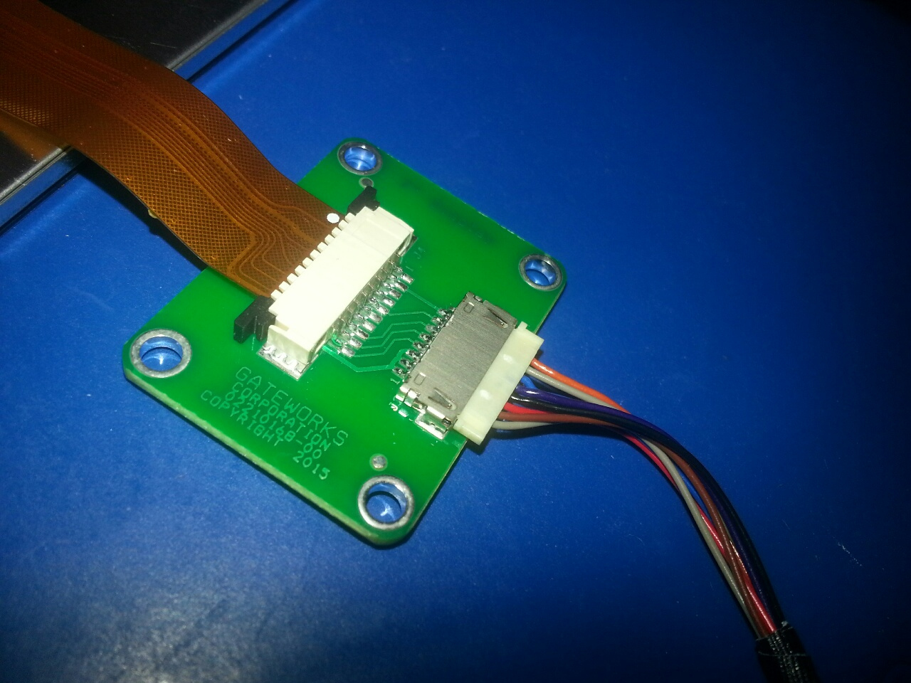
- Plug the small ribbon cable on the LCD into the adapter board slot as pictured

- Take the GW10109/GW16113/GW16114 Cable and plug the side with two connectors into the LCD and the Adapter board.

- Plug the single end of the cable onto the Ventana board LVDS connector.

Selecting a LCD & Touchscreen Display
Selecting a usable display can be complex. Gateworks has broken down the selection process:
- Size
- Typical sizes range from 4" to 15", with something like 7" the most common
- Backlight
- Voltage - LED's can require a large boost voltage. If this voltage is not available on the board, display driver boards are often created for boosting to a higher voltage. Current must also be taken into consideration. 5V and 3.3V are supplied on the Gateworks SBC 30 pin connector.
- Backlight Adjustment
- PWM - Supported on Gateworks 30 pin connector
- Analog
- Video Interface
- LVDS - Gateworks has a 30 pin LVDS connector as documented on this wiki page.
- Touchscreen
- Capacitive - Similar to most cell phones. More expensive. More sensitive.
- Resistive - Requires a physical press, less sensitive, but good for gloves, etc
- Controller - The touchscreen itself outputs signals that are typically best interpreted via a specific touchscreen controller. This controller then interfaces with the Gateworks SBC. Gateworks has a I2C interface on the LVDS connector for this interface. USB interfaces also exist, but USB is not on the LVDS connector, and thus a separate cable would be needed.
- VERY IMPORTANT: Controller software driver - A touchscreen controller will not work if the proper driver is not loaded in the Linux software. Be sure a driver is supported for this touchscreen controller chip. Look for possibly supported chips here: http://lxr.free-electrons.com/source/drivers/input/touchscreen/?v=3.10
- Bonding - Touchscreens are bonded to LCD displays. Some combinations are pre-bonded but otherwise bonding is a very complex process and requires very expensive machinery. It is highly recommended that the LCD and touchscreen be bought pre-bonded.
- Cabling
- Often cabling will need to be created to mate connectors. Gateworks has a 30 pin connector that may have to mate to a 20 pin connector along with backlight and touchscreen. For cabling, companies such as Quadrangle can create a custom cables.
Adding Support for a New LCD
Adding support for a new LCD requires modifying the source code of the software.
While the code changes are fairly simple, determining the timings can be complicated and involves translating timings from the manufacturers datasheet to the display timings that Linux drivers need.
Determining Timing values
You can easily experiment with different timing values by using the Ventana bootloader 'fixfdt' script to alter the timings of the default display which is the 'hsd100pxn1' (unless you've changed it by setting the display env variable). Note that the timings represented in the device-tree are hex values.
Here is an example of setting up a fixfdt script for overriding the values and setting them for a 1280x800 pixel display (0x500 x 0x320) with a refresh rate of 60Hz (0x3c) and a clock-frequency of 68930000Hz (0x41bc9d0) and margins of 220/40/21/7:
setenv timing_path '/soc/aips-bus@02000000/ldb@020e0008/lvds-channel@0/display-timings/hsd100pxn1'
setenv fixfdt '\
 fdt addr ${fdt_addr}; \
 fdt set ${timing_path} clock-frequency <0x41bc9d0>; \
 fdt set ${timing_path} hactive <0x500>; \
 fdt set ${timing_path} vactive <0x320>; \
 fdt set ${timing_path} hback-porch <0xdc>; \
 fdt set ${timing_path} hfront-porch <0x28>; \
 fdt set ${timing_path} vback-porch <0x15>; \
 fdt set ${timing_path} vfront-porch <0x0x7>; \
 fdt set ${timing_path} hsync-len <0x3c>; \
 fdt set ${timing_path} vsync-len <0xa>; \
'; saveenv; reset
The display timing device-tree bindings are documented in Documentation/devicetree/bindings/video/display-timing.txt.
U-Boot Bootloader LCD display support
The Ventana U-Boot Bootloader specifies an array of displays via the displays variable here. The struct display_info_t structure (defined here) defines a bus/addr, pixel format, detect function, enable function, and video mode which includes a unique name, resolution and timings details. The panel env variable is used by U-Boot to determine which panel to configure and the value must match one of the video mode names in the array. Note that the display env variable can also be used for configuring the display for the Linux kernel (see below).
The video-mode structure is described https://lxr.missinglinkelectronics.com/uboot/include/linux/fb.h#L598 - some of it is self-explanatory and comes straight out of the manufacturers datasheet and some is not:
- name - unique name that needs to match the
paneland/ordisplayenv variable - refresh - refresh rate
- xres/yres - display resolution or 'active pixels'
- left_margin/right_margin/upper_margin/lower_margin - the margins (in units of pixclock periods) for video blanking
- pixclock - the frequency of the pixel clock (from the datasheet) (in units of picoseconds) (for example, 64MHz would be pixclock=(1/64000000)*100000=15625)
- hsync_len/vsync_len - hsync and vsync period (in units of pixclock periods)
- sync - flags describing the polarity details of the sync signals (see here) - for LVDS displays this is always FB_SYNC_EXT
- vmode - videomode flags (see here) - for LVDS displays this is always FB_VMODE_NONINTERLACED
- flag
As an example, lets take the 'AUO G101EVN01.0' 1280x800 10.1" LVDS display:
- AUO G101EVN01.0 datasheet
- 1280x800 active pixels (6.5.1 Timing Characteristics)
- pixclock = (1/68.93MHz)*(1000000) = 14507 (68.93MHz is from typical clock frequency specified in 6.5.1 Timing Characteristics)
We would add an additional structure to displays in board/gateworks/gw_ventana/gw_ventana.c:
{
        /* AUO G101EVN01.0 */
        .bus    = 0,
        .addr   = 0,
        .detect = NULL,
        .enable = enable_lvds,
        .pixfmt = IPU_PIX_FMT_LVDS666,
        .mode   = {
                .name           = "AUOG101EVN01.0",
                .refresh        = 60,
                .xres           = 1280,         /* 1024x768 active pixels */
                .yres           = 800,
                .pixclock       = 14507,        /* 68.93MHz */
                .left_margin    = 220,
                .right_margin   = 40,
                .upper_margin   = 21,
                .lower_margin   = 7,
                .hsync_len      = 60,
                .vsync_len      = 10,
                .sync           = FB_SYNC_EXT,
                .vmode          = FB_VMODE_NONINTERLACED
        }
}
After rebuilding the bootloader and updating the board, we can set panel as such:
Ventana > setenv panel AUOG101EVN01.0; saveenv; reset
Depending on how you connected the LVDS display to the Gateworks Ventana board, you may need to manipulate the two GPIO signals going to the LVDS connector:
- GPIO1_IO10 (gpio10 BACK_EN#)
- GPIO1_IO18 (gpio18 BACK_ADJ) (in the kernel this would be the backlight PWM signal)
By default these are configured in the enable_lvds function as gpio10/BACK_GPIO low, and gpio18/BACK_ADJ high. The gpio18/BACK_ADJ signal is configured as a PWM for backlight brightness in the kernel, however the Ventana bootloader does not have PWM support so this is defaulted to a gpio out driven high (which would be 100% backlight). The gpio10/BACK_GPIO signal can be used to connect to a RST# or EN# signal and if connected must be adjusted for your display. As the bootloader defaults this to output-low, you may need to change that to output high if you connected it to an active-high enable:
Ventana > setenv preboot 'gpio set 10'; saveenv; reset
Note that there is no support for touch-screen control in the Ventana bootloader.
Bootloader boot script
Most Gateworks BSP's load and execute a U-Boot bootscript from the OS that performs any OS specific kernel configuration. The bootloader will load and execute a script (if found) from the first ext2/3/4 partition on a block storage device, or the ubi boot/rootfs volume of a NAND ubi partition named boot/6x_bootscript-ventana. The source for these scripts can be found here:
One of the things the Yocto and Android bootscripts do is configure the 'video=' kernel parameters based on the display env variable to values that are appropriate for the kernels used there. You can always override this by setting the bootloader 'video' env parameter manually, or you can add to the bootloader script to configure the parameters for your device specifically.
As an example, lets take the 'AUO G101EVN01.0' 1280x800 10.1" LVDS display:
- for Yocto using the 3.14 kernel (see wiki:Yocto/Video_Out Yocto/Video_Out)
setenv video 'video=mxcfb0:dev=ldb,LDB-XGA,if=RGB666 video=mxcfb1:off video=mxcfb2:off video=mxcfb3:off' - for Android using the 3.14 kernel:
setenv video 'video=mxcfb0:dev=ldb,bpp=32,LDB-XGA,if=RGB666 video=mxcfb1:off video=mxcfb2:off video=mxcfb3:off' - for OpenWrt 16.02 using the 4.4 kernel (see wiki:linux/display):
setenv video 'video=LVDS-1:1280x800@60M video=HDMI-A-1:d'
Linux Kernel LCD display support
For Linux Kernel support, the device-tree specifies the display timings. The device tree file you modify will depend on the board you are using, such as GW52xx, GW53xx, or GW54xx. For example, the GW53xx device-tree in the Gateworks 3.14 vendor kernel is here.
The Ventana kernel specifies multiple display-timings within the lvds-channel@0 node and the native-mode property points to which one to use. This native-mode property gets set by the bootloader prior to booting the kernel based on the display env variable. Therefore, you can either add an additional timing and set the display variable, or you can simply overwrite the default timing0.
The display timing device-tree bindings are documented in Documentation/devicetree/bindings/video/display-timing.txt. All values are identical to those used in the bootloader except that the bootloader uses 'pixclock' which is in units of picoseconds, and the kernel uses 'clock-frequency' in units of Hz.
As an example, lets take the 'AUO G101EVN01.0' 1280x800 10.1" LVDS display:
- AUO G101EVN01.0 datasheet
- 1280x800 active pixels (6.5.1 Timing Characteristics)
- pixclock = (1/68.93MHz)*(1000000) = 14507 (68.93MHz is from typical clock frequency specified in 6.5.1 Timing Characteristics)
We would add an additional device-tree node to display-timings in arch/arm/boot/dts/imx6qdl-gw53xx.dtsi (to add it to the GW53xx - add it to the other board dtsi files as needed)
timing3: g101evn010 {
     clock-frequency = <68930000>;
     hactive = <1280>;
     vactive = <800>;
     hback-porch = <220>;
     hfront-porch = <40>;
     vback-porch = <21>;
     vfront-porch = <7>;
     hsync-len = <60>;
     vsync-len = <10>;
     linux,phandle = <&timing3>;
};
- Note that 'timing3' needs to be unique from the other timings already defined
- Note the 'linux,phandle' property that needs to reference itself (timing3 in this example). This is un-conventional but necessary in order for the Ventana U-Boot bootloader to adjust the 'native-timing' property to match (case-insenstive) the display named 'G101EVN010' in this example based on the env variable.
Now, after our kernel device-tree is built and updated on our target board we can set the display variable as follows:
Ventana > setenv display G101EVN010; saveenv; reset
To verify the device tree has the correct information once the board is booted, browse through the directory structure for the display-timings, and you should see your display:
root@ventana:~# ls /proc/device-tree/soc/aips-bus\@02000000/ldb\@020e0008/lvds-channel\@0/display-timings/
dlc700ctp    dlc700jmgt4  dlc800figt3  hsd100pxn1   name         native-mode
Then, to verify the correct information, you can use something like the following command to see the values:
root@ventana:~# hexdump -C /proc/device-tree/soc/aips-bus\@02000000/ldb\@020e0008/lvds-channel\@0/display-timings/dlc700ctp/hactive
00000000  00 00 03 20                                       |... |
00000004
The hex value of 0x0320 is decimal 800, which is correct for this example, of a horizontal active resolution of 800 pixels.
If your display has a touch-screen controller you need to add support for that separately which typically involves enabling a driver and adding a device-tree binding for that driver (not described here).
Attachments (4)
- lcdadapterboard.jpg (354.3 KB ) - added by 7 years ago.
- lcdcables.jpg (420.0 KB ) - added by 7 years ago.
- lcdconnection.jpg (437.3 KB ) - added by 7 years ago.
- ventanalvdsconnector.jpg (478.9 KB ) - added by 7 years ago.
Download all attachments as: .zip