Serial Peripheral Interface Bus (SPI)
The Serial Peripheral Interface bus is a synchronous serial communication interface specification used for short distance communication primary in embedded systems. The interface was originally developed by Motorola and can be used in a master or slave configuration. It is typically used as a 3-wire bus containing the following signals (other than power and ground and chip-selects):
- SCLK
- MISO
- MOSI
- SS# (Optional Slave Select)
SPI bus FAQ
SPI can be a multi-slave bus if chip selects are used which are asserted by the host controller to enable one device at a time.
The clock rate can differ between SPI slave devices as only the one with the asserted (active low) chip-select is active.
The SPI bus on Newport is capable of clocking up to 50Mhz, although the MCP2515 can only clock up to 10Mhz.
The clock rate dictates how long SPI transactions take in real-time, therefore you want to use the highest rate possible to minimize the amount of time a chip is owning the bus.
The type of activity being performed with each slave device dictates how often and how long each device is owning the bus.
The SPI subsystem has a SPI message queue which is handled as a FIFO. See the Elixir page linked below for more details.
Your CPU frequency, co-processors frequency, and kernel tuning will dictate how often the SPI host is serviced in order to service the queue. Questions related to SPI host servicing and queuing should be sent to the linux-spi mailing list linux-spi@vger.kernel.org
References:
- http://en.wikipedia.org/wiki/Serial_Peripheral_Interface_Bus
- https://www.kernel.org/doc/html/latest/driver-api/spi.html
- https://elixir.bootlin.com/linux/latest/source/Documentation/spi/spi-summary.rst
On-Board SPI controllers
The following Gateworks boards support on-board SPI controllers:
| Family | Board | Connector | Notes |
|---|---|---|---|
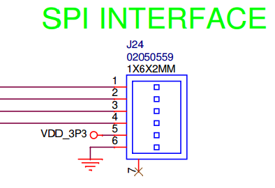
| Catalina | GW92xx | J22 | SPI4 CS0=TPM, CS1=FSA1, CS2=FSA2, CS3=J22 |
| Venice | GW82xx | J7 | SPI2 CS0=TPM, CS1=J7, CS2=FSA1, CS3=FSA2 |
| GW81xx | SPI2 CS0=TPM, CS1=FSA1 | ||
| GW7xxx | See HW Manual | single CS2; ecspi2 dts node | |
| Newport | GW640x | J8 | single CS2; spi_7_0 dts node; half-duplex1; modes 13 |
| GW630x | J8 | single CS2; spi_7_0 dts node; half-duplex1; modes 13 | |
| GW620x | J5 | single CS2; spi_7_0 dts node; half-duplex1; modes 13 | |
| GW610x | J10 | single CS2; spi_7_0 dts node; half-duplex1; modes 13 | |
| Ventana | GW54xx-E+ | J24 | single CS2; ecspi2 dts node |
| GW522x | J32 | single CS2; ecspi3 dts node | |
| GW5910 | J11 | single CS2; ecspi3 dts node |
- Note that the Cavium ThunderX SPI controller in the CN80XX on the Newport Product family only supports half-duplex SPI transfers. In hardware the connections are full duplex MISO and MOSI lines are not shared, in software reads and writes need to be sent in separate calls, rather than simultaneously (full duplex). Drivers that use full-duplex transactions can be modified to support half-duplex (see can:mcp251x: convert driver to half-duplex SPI as en example.
- While only a single Chip Select (CS) is brought out to an external connector any of the DIO pins routed to ARM GPIO's can be used as additional chip-selects. For Ventana this is done via device-tree pinctrl and for Newport this must be done via a PINSEL GPIO (contact support@…)
- Note that the Cavium ThunderX SPI controller in the CN80XX only supports SPI mode 1 (which clock polarity (CPOL/CKP) is low, clock phase (CPHA) is high, and Clock edge (CKE/NCPHA) is low.
See the below product family specific sections for pinout details.
Catalina
SPI is brought out on most Venice SBCs and often shared between multiple devices/connectors each having their own chip-select.
To understand the chip select routing refer to the base-board's device-tree.
The i.MX95 LPSPI interfaces feature:
- Up to 30 MHz when operating in master mode.
- Operating Modes: Each instance is fully configurable to act as either an SPI Master or SPI Slave.
- Word Size: Supports flexible data frame formatting with a configurable word size up to 32-bit.
- Data Buffering: Integrated internal FIFO buffers for both transmit and receive channels to minimize data loss.
- DMA Integration: Direct support for DMA (Direct Memory Access) transmit and receive requests, allowing background transfers with minimal CPU overhead.
- Clock Controls: Fully configurable clock polarity (CPOL) and clock phase (CPHA) settings.
See Catalina chip select portion of device tree for GW9200 here: https://github.com/Gateworks/linux-catalina/blob/v6.18.20-catalina/arch/arm64/boot/dts/freescale/imx95-catalina-gw92xx.dtsi#L543
Venice
SPI is brought out on most Venice SBCs and often shared between multiple devices/connectors each having their own chip-select.
To understand the chip select routing refer to the base-board's device-tree and refer to the hardware manual for pin outs.
Gateworks uses the eCSPI modules of the i.mx8 for external connections. The FlexSPI or QSPI is not used, as this is typically used for flash devices, etc.
While the IMX8MM Datasheet states SPI suports data rates of up to 52Mbits/s the timing details show the following for eCSPI{1,2,3} clock:
- Master mode (Table 30) clk: 23MHz/66Mhz read/write
- Slave mode (Table 31) clk: 66Mhz/23MHz read/write
While the IMX8MP Datasheet states SPI suports data rates of up to 52Mbits/s the timing details shows the following for eCSPI{1,2,3} clock:
- Master Mode (Table 37)
| bus | muxed from | master read (Mhz) | master write (MHz) |
| SPI1 | I2C1/I2C2 | 25 | 50 |
| SPI1 | SPI2 | 30 | 60 |
| SPI2 | SD2 | 30 | 60 |
| SPI2 | SPI2 | 25 | 50 |
| SPI2 | I2C3/I2C4 | 20 | 40 |
| SPI3 | UART1/UART2 | 25 | 50 |
- Slave Mode (Table 38)
- 66Mhz/23MHz read/write
Typical pins exposed are:
- MOSI
- MISO
- SCLK
- SS0# (This is chip select 0 but note that Linux and U-Boot support any gpio as a chip select)
USB SPI controllers
A SPI master can also be added via USB expansion. For example:
- GW16113 firmware-flexible USB 2.0 FS expansion
- Commell MPX-24794S USB 2.0 FS SPI/I2C/GPIO expansion
Linux spidev userspace API
SPI devices have a limited userspace API, supporting basic half-duplex read() and write() access to SPI slave devices referred to as spidev. Using ioctl() requests, full duplex transfers and device I/O configuration are also available.
Some reasons you might want to use this programming interface include:
- Prototyping in an environment that's not crash-prone; stray pointers in userspace won't normally bring down any Linux system.
- Developing simple protocols used to talk to micro-controllers acting as SPI slaves, which you may need to change quite often.
Of course there are drivers that can never be written in userspace, because they need to access kernel interfaces (such as IRQ handlers or other layers of the driver stack) that are not accessible to userspace.
Userspace access to SPI devices is done through the /dev/spidev<bus>.<chip-select> device interface. In order to use this you must have spidev enabled in the kernel (CONFIG_SPI_SPIDEV) and have a spidev node defined under the SPI controller in the device-tree.
In order to support spidev a spidev child node needs to be present in the device-tree under the SPI host controller.
Examples:
- Venice / VeniceFLEX:
- GW71xx (imx8mm-venice-gw71xx.dtsi), GW72xx (imx8mm-venice-gw72xx.dtsi), GW73xx (imx8mm-venice-gw73xx.dtsi), and GW82xx all provide ecspi2 to an off-board connector with GPIO5_IO13 as a chip select:
/* off-board header */
&ecspi2 {
        pinctrl-names = "default";
        pinctrl-0 = <&pinctrl_spi2>;
        cs-gpios = <&gpio5 13 GPIO_ACTIVE_LOW>;
        status = "okay";

        /*
         * SPI_CS0 goes to the off-board connector
         * compatible must match a string from drivers/spi/spidev.c's compatible list
         */
        spidev0: spidev0@0 {
                compatible = "rohm,dh2228fv";
                reg = <0>;
                spi-max-frequency = <10000000>;
        };
};
- GW71xx (imx8mm-venice-gw71xx.dtsi), GW72xx (imx8mm-venice-gw72xx.dtsi), GW73xx (imx8mm-venice-gw73xx.dtsi), and GW82xx all provide ecspi2 to an off-board connector with GPIO5_IO13 as a chip select:
- Catalina GW9200 (Note TPM is on the first chip select reg=0x0, so user header J22 is reg=0x3, which is chip select 4, but 3 for zero based numbering. spidev3 in the example below is just an example for J22 header)
&lpspi4 {
        pinctrl-names = "default";
        pinctrl-0 = <&pinctrl_lpspi4>;
        cs-gpios = <&gpio2 24 GPIO_ACTIVE_LOW>, /* CS0 TPM */
                   <&gpio5 14 GPIO_ACTIVE_LOW>, /* CS1 FSA1 */
                   <&gpio5 13 GPIO_ACTIVE_LOW>, /* CS2 FSA2 */
                   <&gpio5 12 GPIO_ACTIVE_LOW>; /* CS3 J22 */
        status = "okay";

        tpm@0 {
                compatible = "atmel,attpm20p", "tcg,tpm_tis-spi";
                reg = <0x0>;
                spi-max-frequency = <20000000>;
        };
        spidev3: spidev@3 {
                compatible = "rohm,dh2228fv";
                reg = <0x3>;
                spi-max-frequency = <20000000>;
        };
};
In the above examples, adjust 'spi-max-frequency' according to the max frequency your slave device can support.
For instructions on compiling and updating a device-tree see linux/devicetree
An application using spidev would include the <linux/spi/spidev.h> header file.
The compatible string doesn't actually do anything but must match one that the linux drivers/spi/spidev.c module binds to:
static const struct of_device_id spidev_dt_ids[] = {
        { .compatible = "abb,spi-sensor", .data = &spidev_of_check },
        { .compatible = "cisco,spi-petra", .data = &spidev_of_check },
        { .compatible = "dh,dhcom-board", .data = &spidev_of_check },
        { .compatible = "elgin,jg10309-01", .data = &spidev_of_check },
        { .compatible = "gocontroll,moduline-module-slot", .data = &spidev_of_check},
        { .compatible = "lineartechnology,ltc2488", .data = &spidev_of_check },
        { .compatible = "lwn,bk4", .data = &spidev_of_check },
        { .compatible = "lwn,bk4-spi", .data = &spidev_of_check },
        { .compatible = "menlo,m53cpld", .data = &spidev_of_check },
        { .compatible = "micron,spi-authenta", .data = &spidev_of_check },
        { .compatible = "rohm,bh2228fv", .data = &spidev_of_check },
        { .compatible = "rohm,dh2228fv", .data = &spidev_of_check },
        { .compatible = "semtech,sx1301", .data = &spidev_of_check },
        { .compatible = "silabs,em3581", .data = &spidev_of_check },
        { .compatible = "silabs,si3210", .data = &spidev_of_check },
        {},
};
For more info see:
Attachments (2)
- GW5220-SPI-INTERFACE.png (13.4 KB ) - added by 9 years ago.
- spi2388.png (32.8 KB ) - added by 9 years ago.
Download all attachments as: .zip