
GW16160 - Precision GNSS M.2 Card
The GW16160 is a precision GNSS M.2 Card featuring the Septentrio mosaic-X5 multi-frequency receiver.
Read more on the official product page here: https://www.gateworks.com/products/wireless-options/gw16160-septentrio-mosaic-precision-gnss-m2-card/
Features
The GW16160 features a Septentrio Mosaic-X5 Precision GNSS receiver on an M.2 A/E Key card with:
- 2-wire UART (COM1) (optional)
- USB 2.0 (USB1, USB2, RNDIS, USB Mass Storage)
- RESET# (connected to Mosaic active-high NRST_IN#)
- PPS_OUT, PPS_IN
- EVENTA_IN
- 100Mbps Ethernet interface (Optional)
- 4 LEDs: Power, GPLED, GPLED2, LOGLED
- microSD socket (for data logging)
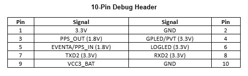
M.2 Pinout
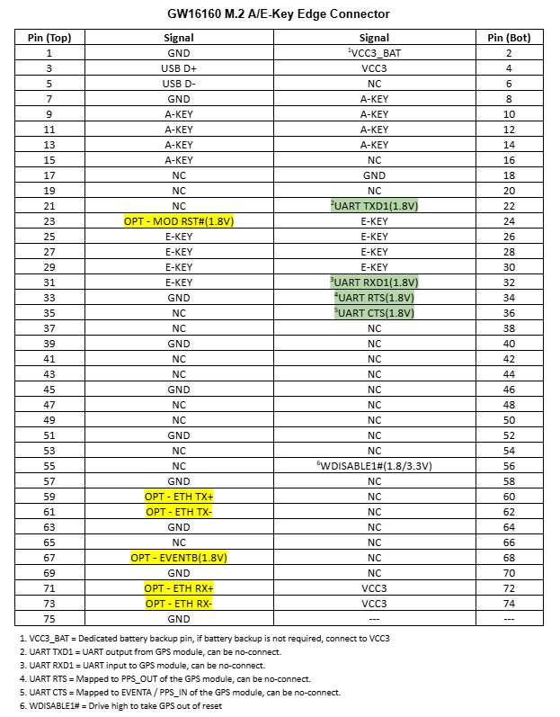
The following tables provide the connector pinouts for the 10-pin debug header and the M.2 A/E-Key connector. Optional signals for the Gateworks adapter are highlighted in yellow and have a “OPT” label. These are no-connects on the standard board model, contact sales for special models with support for these signals. The UART signals highlighted in green are connected to the GNSS module but are not required for module operation and can be no-connects. The 10-pin debug header is a 0.050” dual row thru-hole connector and is not loaded on the standard model but can be easily probed.
M.2 Pinout:
- M2.56 RST#(1.8/3.3V); must be driven high to take Mosaic-X5 out of reset
- M2.2 VDD_BAT
- M2.3 USB_DP
- M2.5 USB_DM
- M2.22 UART_TXD (1.8V) output from card
- M2.32 UART_RXD (1.8V) input to card
- M2.34 PPS (1.8V) output from card; normally UART_RTS; via R23 (loaded)
- M2.36 EVENTA (1.8V) input to card; normally UART_CTS; via R24 (loaded)
- M2.4,72,74 VDD_3P3
- M2.1,7,33,39,45,51,57,63,69,75 GND
- M2.59 ENET_TX+; optional
- M2.61 ENET_TX-; optional
- M2.71 ENET_RX+; optional
- M2.73 ENET_RX-; optional
- M2.67 EVENTB(1.8V); optional; via R22 (unloaded)


Antenna
There is one antenna port for the Mosaic X5.
To get started, a recommended antenna is the Yokowo Manufacturing of America YOZ-52728ZZ01-YM available here
A smaller option we like is the TW7972, and a bit larger one for machine control-type applications (or car tests) is the PolaNt* MC.v2.
A list of antennas from Septentrio is here: https://www.septentrio.com/en/support/product-resources/supportresources/gnssantennas
The unloaded second antenna port can be used for different Septentrio GNSS receivers that are an optional load.
Compatibility
The GW16160 requires an M.2 E-Key socket with USB2.0 and M2.56 RST#.
The only E-Key sockets on Gateworks boards are:
- GW16151 MiniPCIe to M.2 E-Key Adapter - works with the standard board that has reset on Pin 56 but it won't work with a custom board with pin 23 as reset (won't bring Mosaic out of reset).
- GW820x+GW16FE0 in FSA2 - SDIO_RESET# is pin23 and is GPIO2_10. To take out of reset you can add 'gpio set gpio2_10' to U-Boot scripts (ie preboot). FSA1 does not connect pin23. Pin 56 reset is supported by both FSA1 and FSA2.
Examples:
- GW820x+GW16FE0 in FSA2:
- set GPIO in U-Boot:
setenv preboot "$preboot; gpio set gpio2_10"
saveenv
- set GPIO in U-Boot:
Reset
The Mosiac-X5 NRST_IN# needs to be floating (internal pu) or driven high at 3.3V to allow the card out of reset.
The standard GW16160 uses M.2 Pin 56 (W_DISABLE1#) as the source of this reset.
The GW16160-A revision uses pin 23 SDIO_RESET# for reset which is not normally driven:
- take out of reset when mounted on a GW16FE0 in FSA2 of a GW820x where SDIO_RESET# is GPIO2_10:
- via U-Boot
gpio set gpio2_10 - via Linux (gpio2_10 is gpio-42)
echo 42 > /sys/class/gpio/export
echo out > /sys/class/gpio/gpio42/direction
echo 0 > /sys/class/gpio/gpio42/value # drive low to reset
echo 1 > /sys/class/gpio/gpio42/value # release reset
- via U-Boot
Reset Loading Options:
- M.2 Pin 56 W_DISABLE1# (default for GW16160-B+) via R25
- Resistor R20 can be loaded and U7 unloaded to directly connect these if used in a socket where this pin is 3.3V
- U7 can be unloaded and the internal PU will allow the Mosiac out of reset without the ability to reset it via hardware
USB Interface
When powered and out of reset, the Mosiac-X5 USB interface enumerates on the USB bus with a VID/PID of 0x152a:0x85c0:
Bus 003 Device 004: ID 152a:85c0 Thesycon Systemsoftware & Consulting GmbH Septentrio USB Device
The USB device provides 7 endpoints:
- {0,1} - RNDIS Ethernet device (Linux rndis_host driver)
- {2,3} - CDC ACM device (Linux cdc_acm driver)
- {4,5} - CDC ACM device (Linux cdc_acm driver)
- 6 - USB Mass Storage device (Linux usb-storage driver)
A Linux kernel would show:
[  213.543608] usb 3-1.2: new high-speed USB device number 5 using xhci-hcd
[  213.653262] usb 3-1.2: New USB device found, idVendor=152a, idProduct=85c0, bcdDevice= 3.14
[  213.661651] usb 3-1.2: New USB device strings: Mfr=1, Product=2, SerialNumber=3
[  213.668987] usb 3-1.2: Product: Septentrio USB Device
[  213.674075] usb 3-1.2: Manufacturer: Septentrio
[  213.678628] usb 3-1.2: SerialNumber: 3838051
[  213.799064] rndis_host 3-1.2:1.0 eth0: register 'rndis_host' at usb-xhci-hcd.1.auto-1.2, RNDIS device, 1a:32:02:9
9:15:45
[  213.814494] cdc_acm 3-1.2:1.2: ttyACM0: USB ACM device
[  213.822420] cdc_acm 3-1.2:1.4: ttyACM1: USB ACM device
[  213.828650] usb-storage 3-1.2:1.6: USB Mass Storage device detected
[  213.835529] scsi host0: usb-storage 3-1.2:1.6
[  213.864384] rndis_host 3-1.2:1.0 enx1a3202991545: renamed from eth0
[  214.868534] scsi 0:0:0:0: CD-ROM            Linux    File-CD Gadget   0314 PQ: 0 ANSI: 2
[  214.877127] scsi 0:0:0:1: Direct-Access     Linux    File-CD Gadget   0314 PQ: 0 ANSI: 2
[  214.886483] sr 0:0:0:0: Power-on or device reset occurred
[  214.893005] sr 0:0:0:0: [sr0] scsi-1 drive
[  214.903049] sr 0:0:0:0: Attached scsi CD-ROM sr0
[  214.908064] sr 0:0:0:0: Attached scsi generic sg0 type 5
[  214.914321] sd 0:0:0:1: Attached scsi generic sg1 type 0
[  214.914851] sd 0:0:0:1: Power-on or device reset occurred
[  214.926006] sd 0:0:0:1: [sda] Media removed, stopped polling
[  214.932590] sd 0:0:0:1: [sda] Attached SCSI removable disk
USB ACM interfaces
The 2x USB ACM interfaces are represented by USB1 and USB2 Connection Descriptors (CD) and would typically enumerate as /dev/ttyACM0 and /dev/ttyACM1.
Examples:
screen /dev/ttyACM0 # USB1
screen /dev/ttyACM1 # USB2
RNDIS Ethernet device
The RNDIS Ethernet interface (not to be confused with the RMII Ethernet) provides a built-in web-server on port 80 on a fixed IP of 192.168.3.1
To utilize this you can put the interface in a bridge with your primary network device.
Example:
- GW8201 where eth0 is your LAN connection, eth1 is the PCI GbE, eth2 (or usb0) would be the Mosaic-X5 RNDIS interface you can put eth0 and eth2 (or usb0) in a bridge
- With the following /etc/network/interface (recommended):
allow-hotplug eth0 auto br0 iface br0 inet dhcp bridge_ports eth0 eth2 #eth2 could be defined as usb0 bridge_stp off bridge_fd 0 bridge_maxwait 0 - Manually (not recommended):
brctl addbr br0
brctl addif br0 eth0
brctl addif br0 eth2 #eth2 could be defined as usb0
udhcpc br0
- With the following /etc/network/interface (recommended):
After bringing up the bridge and the bridge getting a network address give your host computer a static IP on the 192.168.3/24 network and you can open a URL to 192.168.3.1 to access the web admin.
Use the ifconfig command to be sure usb0 or eth2 is listed and bring the interface up with the command:
ifconfig usb0 up
USB Mass Storage interface
The USB Mass storage interface allows access to the SD interface on the Mosaic-X5.
By default the Mosaic-X5 will mount the microSD internally to be used for highly configurable logging represented as the DSK1 connection descriptor (CD). If you unmount this internally it is made available via the USB Mass Storage device.
SD Interface
The SD interface on the Mosaic-X5 is a 1-bit SDIO device which goes to a MicroSD socket on the GW16160.
Receiver config examples:
- use the 'LstDiskInfo,DSK1' receiver command to obtain info about it:
LstDiskInfo,DSK1
---->
$-- BLOCK 1 / 0 C
<?xml version="1.0" encoding="ISO-8859-1" ?>
<DiskInfo version="0.1">

---->
$-- BLOCK 2 / 0 C
  <Disk name="DSK1" total="7931641856" free="7931449344" >
    <File name="log.nma" size="131072" />
  </Disk>
</DiskInfo>
- format it:
exeManageDisk, DSK1, Format
- Log NMEA GPS GGA 1Hz to it
setNMEAOutput, Stream1, DSK1
setNMEAOutput, Stream1, , GGA
setNMEAOutput, Stream1, , , sec1
UART Interface
The 2-wire UART on the GW16160 is routed to COM1 on the Mosaic-X5.
By default COM1 is configured for 115200bd 8N1 no flow control. You can use 'getCOMSettings' and 'setCOMSettings' to configure this.
With a GW16160 mounted on a GW8201 with a GW16FE0 in FSA2 this is /dev/ttymxc2:
#bash
screen /dev/ttymxc2 115200,cs8 # UART3 (FSA#2)
picocom /dev/ttymxc2 -b 115200 --omap lfcr #picocom option
Example output:
$GPGGA,224309.00,,,,,0,00,,,M,,M,,*46
$GPGGA,224310.00,,,,,0,00,,,M,,M,,*4E
$GPGGA,224311.00,,,,,0,00,,,M,,M,,*4F
$GPGGA,224312.00,,,,,0,00,,,M,,M,,*4C
$GPGGA,224313.00,,,,,0,00,,,M,,M,,*4D
Ethernet Interface
The Ethernet interface is optional and not loaded by default.
The Mosaic-X5 Ethernet interface (not to be confused by the USB RNDIS interface) is provided via RMII to an off-module PHY where we route the TX/RX pairs (4-wires) to reserved pins on the M.2 connector:
- M2.59 ENET_TX+
- M2.61 ENET_TX-
- M2.71 ENET_RX+
- M2.73 ENET_RX-
By default the Mosaic-X5 expects a 50MHz REF_CLK to be provided by the PHY. The PHY on the GW16160 needs the 50MHz REF_CLK to be provided by the MAC and for this to occur you need to apply a firmware update.
If connected to a link partner this provides a 100Mbps interface (which you may need to force via ethtool)
The 'EthernetMode' needs to be enabled in the receiver and this (as well as IPSettings) does not appear to be tracked by the receiver configuration (its stored in NVRAM automatically) and persists across power cycles.
The 'IPSettings' also need to be configured which default to dhcp with a hostname of mosaic-x5-xxxxxxx (where the last 7 digits are the serial number of the receiver). This is not tracked by receiver configuration (its stored in NVRAM automatically) and persists across power cycles.
If using DHCP you can obtain the IPParameters from the receiver via 'lstInternalFile,IPParameters':
lstInternalFile,IPParameters
---->
$-- BLOCK 1 / 1
<?xml version="1.0" encoding="ISO-8859-1" ?>
<ipparameters>
    <interface name="eth0"  type="Ethernet" hostname="mosaic-x5-3838323">
        <hardware addr="8C:1C:DA:52:CE:C5"/>
        <inet addr="192.168.3.176" mask="255.255.255.0" gateway="" mode="dhcp"/>
        <statistics txbytes="1080" rxbytes="151338" internet="Not Tested"/>
    </interface>
    <resolv>
    </resolv>
</ipparameters>
In summary you need the following to use this interface:
- Link partner connected to the 2 pairs configured for 100mbps ethernet
- Firmware update to provide the 50Mhz clk from the Mosaic MAC
- EthernetMode enabled in the receiver
- Either set IPParameters for static IP or read it to get IP settings
LEDs
The following LED's are available on the GW16160:
- Power
- GPLED: configurable
- GPLED2: confiugrable
- LOGLED: off when SD card not present, on when SD card present and mounted, short blinks when logging
The GPLED and GPLED2 can be configured for varios modes
Receiver commands:
getLEDMode # show LED mode for GPLED and GPLED2
setLEDMode,$GPLED,$GPLED2 # DIFFCORLED, PVTLED, TRACKLED, LOGLED, RTKLED:
PPS Output
The PPS output on M.2 pin 34 is highly configurable. The default configuration is to output 1Hz Low2High synchronized with GPS
When the GW16160 is used on a GW8201 with a GW16FE0 in FSA2 pin 34 is UART_RTS which maps to MX8MP_IOMUXC_ECSPI1_SS0GPIO5_IO09.
You can connect this to a pps source via the following dt fragment:
/ {
        pps {
                compatible = "pps-gpio";
                pinctrl-names = "default";
                pinctrl-0 = <&pinctrl_pps>;
                gpios = <&gpio5 9 GPIO_ACTIVE_HIGH>;
        };
};

&iomuxc {
        pinctrl_pps: ppsgrp {
                fsl,pins = <
                        MX8MP_IOMUXC_ECSPI1_SS0__GPIO5_IO09     0x140
                >;
        };
};
Changing the current pps in the GW82xx to this would look like this (although note you can have multiple pps sources):
diff --git a/arch/arm64/boot/dts/freescale/imx8mp-venice-gw82xx.dtsi b/arch/arm64/boot/dts/freescale/imx8mp
-venice-gw82xx.dtsi
index 2b86cc62a41a..137d78c3eb4a 100644
--- a/arch/arm64/boot/dts/freescale/imx8mp-venice-gw82xx.dtsi
+++ b/arch/arm64/boot/dts/freescale/imx8mp-venice-gw82xx.dtsi
@@ -45,7 +45,7 @@ pps {
                compatible = "pps-gpio";
                pinctrl-names = "default";
                pinctrl-0 = <&pinctrl_pps>;
-               gpios = <&gpio4 3 GPIO_ACTIVE_HIGH>;
+               gpios = <&gpio5 9 GPIO_ACTIVE_HIGH>;
        };

        reg_usb2_vbus: regulator-usb2 {
@@ -414,7 +415,7 @@ MX8MP_IOMUXC_SAI3_RXC__GPIO4_IO29   0x106   /* PERST# */
        pinctrl_pps: ppsgrp {
                fsl,pins = <
-                       MX8MP_IOMUXC_SAI1_RXD1__GPIO4_IO03      0x146
+                       MX8MP_IOMUXC_ECSPI1_SS0__GPIO5_IO09     0x146
                >;
        };
To configure PPS via the receiver:
getPPSParameters # default is sec1, Low2High, 0.00, GPS, 60, 5.000000
setPPSParameters,sec1,,,UTC # sync with UTC 1Hz
EventA Input
The EVENTA input signal on the Moasic-X5 routed to M2 pin 36 on the GW16160 and can be configured to trigger various things
When the GW16160 is used on a GW8201 with a GW16FE0 in FSA2 pin 34 is UART_RTS which maps to MX8MP_IOMUXC_ECSPI1_MISOGPIO5_IO08.
To configure this via the receiver:
setEventParameters,+EventB,Low2High,0.0 # set polarity/delay for eventb
setSBFOutput,Stream1,COM1,ExtEvent,OnChange
The integrated web admin will display events as they come in as well
Receiver
The Mosaic-X5 Receiver is highly capable and configurable. It uses Connection Descriptors to refer to its various interfaces:
- COM1 - UART
- USB1 - ttyACM0
- USB2 - ttyACM1
- DSK1 - microSD
The Mosaic-X5 Firmware Reference Guide (available here) destails the capabilities.
You can access the receiver commands in various ways:
- via web admin
- via USB1/USB2:
screen /dev/ttyACM0 # USB1
screen /dev/ttyACM1 # USB2
- via COM1:
screen /dev/ttymxc2 115200,cs8 # GW820x+GW16FE0 FSA2 (UART3)
Configuration:
- There are multiple sets of configs that you can work with
- Current - current config
- Boot - boot up config
- User1 - user defined 1
- User2 - user defined 2
- RXDefault - factory default, not writable
- use 'lstConfigFile, $CONFIG' to show the differences between a config and RXDefault
- use 'exeCopyConfigFile,$SRC,$TARGET' to copy configs
A few examples:
# show help
help
# show COM1 settings
getCOMSettings
# configure COM1 baudrate
setCOMSettings,COM1,baud115200,bits8,No,bit1,none
# log NMEA GGA 1Hz to com1
setNMEAOutput, Stream1,COM1,GGA,sec1
# log NMEA GGA 1Hz to log.nma
setNMEAOutput, Stream1,DSK1,GGA,sec1
# configure both LEDs for LOGLED
setLEDMode, LOGLED, LOGLED
# show differences from factory default for current config
lstConfigFlie, Current
# restore factory defaults
exeCopyConfigFile,RxDefault,Boot
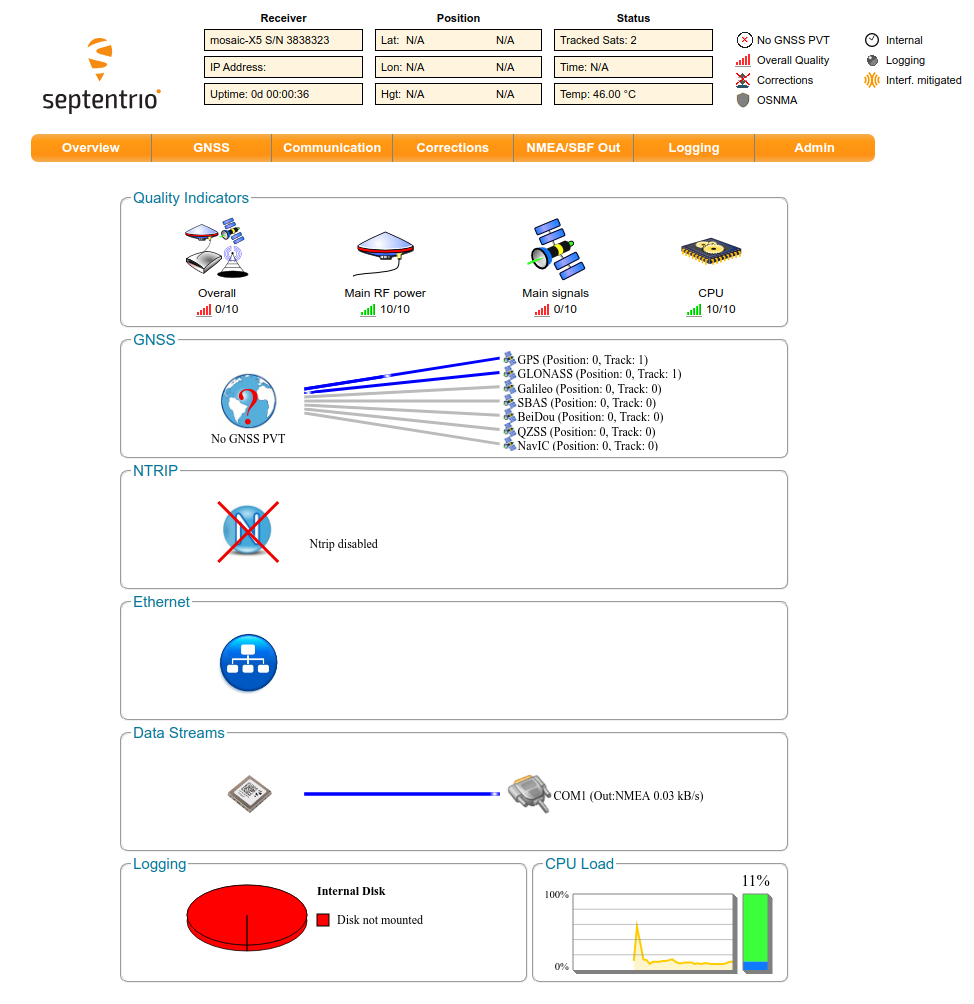
Web Admin Interface GUI
A web admin interface is available over IP (over USB). Setup the IP and bridge with instructions here: #RNDISEthernetdevice
Then, on a host PC that is connected to the same network as the SBC, type in the IP address in the browser (192.168.3.1) and up comes up a GUI web interface shown in the picture below:

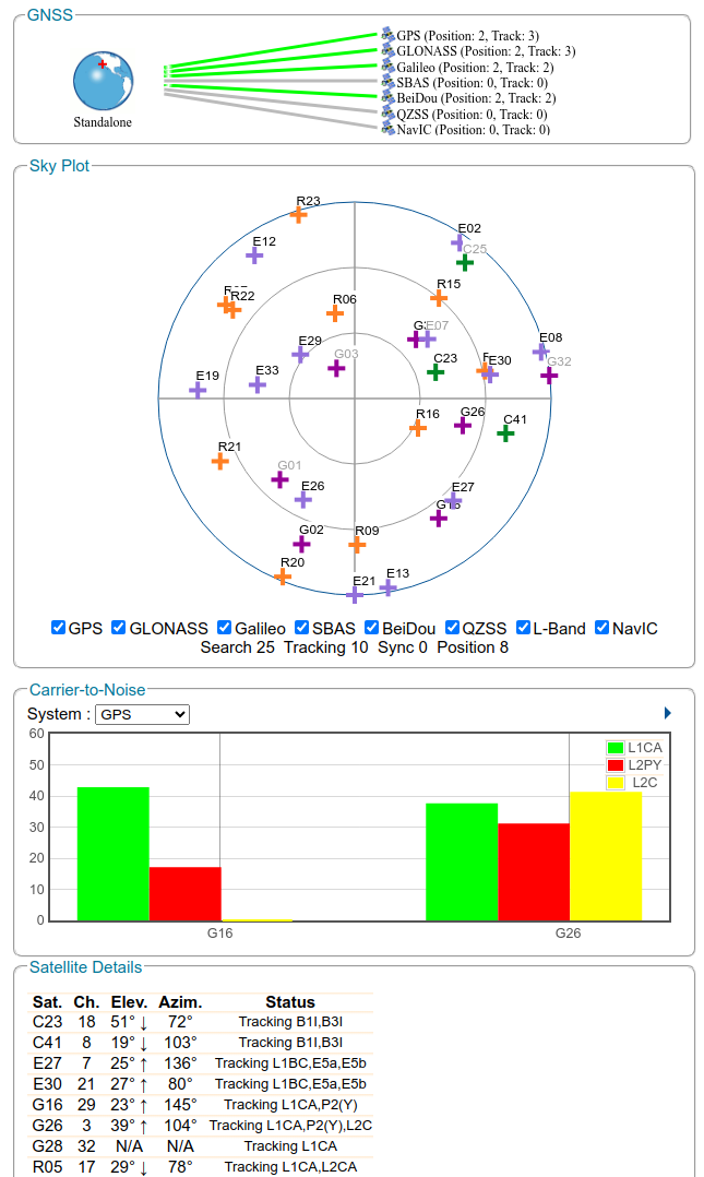
Generally we like to see that the Carrier-to-Noise plot for GPS should show about 2-3 satellites with an L1CA CN0 level around 50 dB-Hz. You can see the CN0 in the web user interface under ‘GNSS’ > ‘Satellites and Signals’. If you want to go deeper, you can log data and analyze the CN0 according to the guidelines here: SBF Analyzer: Carrier to Noise.

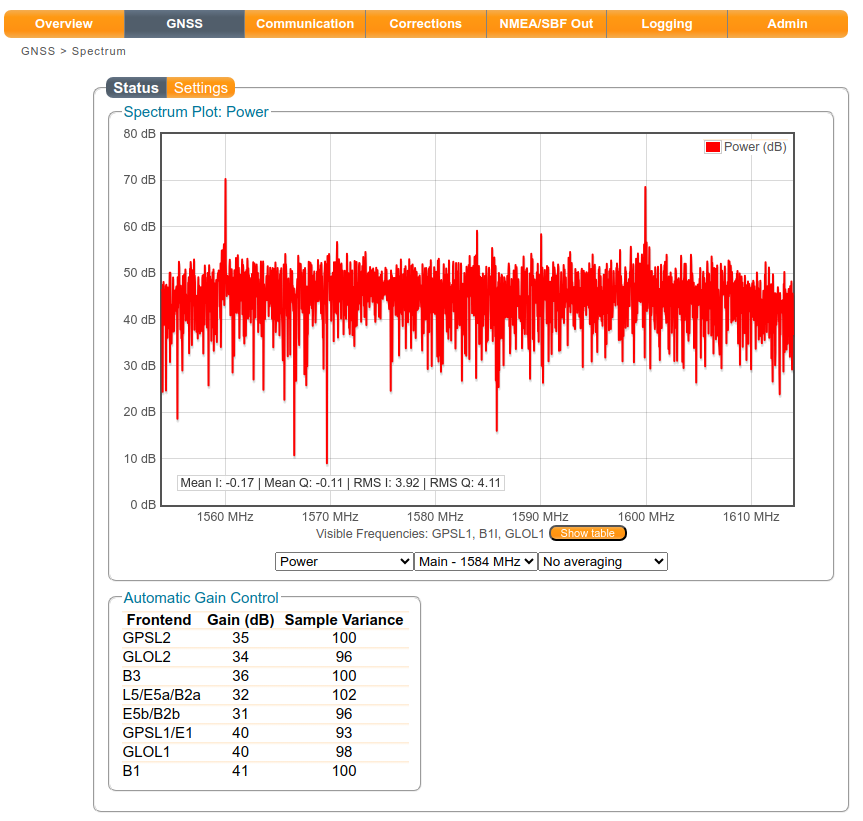
Another basic tool we encourage customers to use to investigate signal levels (and especially interference issues) is to monitor the receiver’s automatic gain control (AGC). AGC is shown in the ‘GNSS’ > ‘Spectrum’ > ‘Status’ page. The AGC should fall between 15 to 50 dB, and the closer to 15 dB (or lower) you go, the more power you're introducing to the receiver input. Thus if AGC is low it likely indicates the presence of interference. You can read more on AGC and the effect that interference will have on this output here: SBF Analyzer - Front End Gain.

Attachments (5)
- 16160webadmin.jpg (126.5 KB ) - added by 12 months ago.
- 16160reception.jpg (111.5 KB ) - added by 12 months ago.
- 16160spectrum.jpg (101.8 KB ) - added by 12 months ago.
- GW16160debug.jpg (22.0 KB ) - added by 6 months ago.
- GW16160pinout.jpg (131.4 KB ) - added by 6 months ago.
Download all attachments as: .zip