| Version 4 (modified by , 85 minutes ago) ( diff ) |
|---|
GW16171 - Precision GNSS M.2 Card
The GW16171 is a precision GNSS M.2 Card featuring the Septentrio mosaic-G5 P6 multi-frequency receiver.
Read more on the official product page here: GW16171 Precision GNSS M.2 Card
Features
The GW1671 features a Septentrio Mosaic-G5 Precision GNSS receiver on an M.2 A/E Key card with:
- 2-wire UART (COM1) (optional)
- USB 2.0 (USB1, USB2)
- RESET# (connected to Mosaic active-high NRST_IN#)
- UART 1.8V
- PPS1 output 1.8V (via UART_RTS pin)
- EVENTA input 1.8V (via UART_CTS pin)
- EVENTB input 1.8V/3.3V (optional, via reserved pin)
- 2 configurable LEDs: GPIO1 GPIO2
- microSD socket (for data logging)
Compared to the Mosaic-X5 on the GW16160 the G5 is a lower footprint and lower power consumption device which lacks the TCP/IP stack and RNDIS interface of the X5.
GW16171 M.2 E-Key Pinout
The following tables provide the connector pinouts for the 10-pin debug header and the M.2 A/E-Key connector.
M.2 Pinout:
- M2.56 W_DISABLE1#(1.8/3.3V) RST# (optional, Mosaic-G5 has a pull-up)
- M2.3 USB_DP (required)
- M2.5 USB_DM (required)
- M2.22 UART_TXD (1.8V) output from card
- M2.32 UART_RXD (1.8V) input to card
- M2.34 PPS1 (1.8V) output from card; normally UART_RTS (loaded)
- M2.36 EVENTA (1.8V) input to card; normally UART_CTS (loaded)
- M2.2,4,72,74 VDD_3P3
- M2.1,7,33,39,45,51,57,63,69,75 GND
- M2.67 EVENTB(1.8V/3.3V); optional (unloaded)
The only signals required other than power and GND are USB_DP and USB_DM.
Gateworks boards with M.2 E-Key sockets:
- Catalina boards with a GW16FE0 FSA M.2 E-Key adapter
- Venice-Flex boards with a GW16FE0 FSA M.2 E-Key adapter
- GW16151 MiniPCIe to M.2 E-Key Adapter
Reset
The Mosiac-G5 NRST_IN# needs to be floating (internal pu) or driven high at 3.3V to allow the card out of reset.
The standard GW16171 uses M.2 Pin 56 (W_DISABLE1#) as the source of this reset.
Antenna
There are two antenna ports for the Mosaic G5. Not all Mosaic-G5 variants support dual antennas however the standard GW16171 with the Mosaic-G5 P6 does:
- ANT1 (Main) is used for postition
- ANT2 (Aux) is used for heading and attitude
Note that you can not use ANT2 without ANT1 however in single Antenna mode you can use only ANT1.
The Mosaic-G5 defaults to Single Antenna mode. Use the getFrontEndMode and setFrontEndMode receiver commands to get/set the mode however note that once you do this you need to also save the config to boot configuration and reboot the receiver:
- Get Antenna mode:
< getFrontendMode > $R: getFrontendMode > FrontendMode, Nominal- Nominal mode (default) will choose the best operating mode depending on your product. Normally this is SingleAnt, but for
products with heading as main purpose, this is DualAnt.
- Set Dual Antenna mode:
setFrontendMode, DualAnt
exeCopyConfigFile, Current, Boot
exeResetReceiver, Hard, none
- Set Single Antenna mode:
setFrontendMode, SingleAnt
exeCopyConfigFile, Current, Boot
exeResetReceiver, Hard, none
- Set Nominal (default) Antenna mode:
setFrontendMode, Nominal
exeCopyConfigFile, Current, Boot
exeResetReceiver, Hard, none
A recommended antenna is the Yokowo Manufacturing of America YOZ-52728ZZ01-YM available here
A smaller option we like is the TW7972, and a bit larger one for machine control-type applications (or car tests) is the PolaNt* MC.v2.
A list of antennas from Septentrio is here: https://www.septentrio.com/en/support/product-resources/supportresources/gnssantennas
USB Interface
When powered and out of reset, the Mosiac-G5 USB interface enumerates on the USB bus with a VID/PID of 0x152a:0x85c0:
Bus 003 Device 004: ID 152a:85c0 Thesycon Systemsoftware & Consulting GmbH Septentrio USB Device
The USB device provides 2 endpoints:
- {0,1} - CDC ACM device (Linux cdc_acm driver)
- {2,3} - CDC ACM device (Linux cdc_acm driver)
A Linux kernel would show:
[  213.543608] usb 3-1.2: new high-speed USB device number 5 using xhci-hcd
[  213.653262] usb 3-1.2: New USB device found, idVendor=152a, idProduct=85c0, bcdDevice= 3.14
[  213.661651] usb 3-1.2: New USB device strings: Mfr=1, Product=2, SerialNumber=3
[  213.668987] usb 3-1.2: Product: Septentrio USB Device
[  213.674075] usb 3-1.2: Manufacturer: Septentrio
[  213.678628] usb 3-1.2: SerialNumber: 3838051
[  213.814494] cdc_acm 3-1.2:1.2: ttyACM0: USB ACM device
[  213.822420] cdc_acm 3-1.2:1.4: ttyACM1: USB ACM device
USB ACM interfaces
The 2x USB ACM interfaces are represented by USB1 and USB2 Connection Descriptors (CD) and would typically enumerate as /dev/ttyACM0 and /dev/ttyACM1.
Examples:
screen /dev/ttyACM0 # USB1
screen /dev/ttyACM1 # USB2
SD Interface
The SD interface on the Mosaic-G5 is a 1-bit SDIO device which goes to a MicroSD socket on the GW16171.
Receiver config examples:
- use the 'LstDiskInfo,DSK1' receiver command to obtain info about it:
< LstDiskInfo, DSK1
 > $R; LstDiskInfo, DSK1
 > <?xml version="1.0" encoding="ISO-8859-1" ?>
 > <DiskInfo version="0.1">
 >   <Disk name="DSK1" total="0" free="0" >
 >     <Dir name="/sdcard/">
 >    </Dir>
 >   </Disk>
 > </DiskInfo>
 >
- Log NMEA GPS GGA 1Hz to it
setNMEAOutput, Stream1, DSK1
setNMEAOutput, Stream1, , GGA
setNMEAOutput, Stream1, , , sec1
Unlike the Mosaic-X5, the Mosaic-G5 has no command to format the disk. You must use other means to format it as FAT32 and have it inserted before the module is powered on.
UART Interface
The 2-wire UART on the GW16171 is routed to COM1 on the Mosaic-G5.
By default COM1 is configured for 115200bd 8N1 no flow control. You can use 'getCOMSettings' and 'setCOMSettings' to configure this and can configure various data streams to output to it. For example on the USB1 or USB2 ACM interfaces:
< getCOMSettings
 > $R: getCOMSettings
 >   COMSettings, COM1, baud115200, bits8, No, bit1, none
 >   COMSettings, COM2, baud115200, bits8, No, bit1, none
< setNMEAOutput, Stream1, COM1, GGA, sec1
 > $R: setNMEAOutput, Stream1, COM1, GGA, sec1
 >   NMEAOutput, Stream1, COM1, GGA, sec1
With a GW16171 mounted on a GW9401 with a GW16FE0 in FSA2 this is /dev/ttyLP4: {{{!#bash screen /dev/ttyLP4 115200,cs8 # UART5 (FSA#2) picocom /dev/ttyLP4 -b 115200 --omap lfcr #picocom option }}}
Example output:
$GPGGA,224309.00,,,,,0,00,,,M,,M,,*46
$GPGGA,224310.00,,,,,0,00,,,M,,M,,*4E
$GPGGA,224311.00,,,,,0,00,,,M,,M,,*4F
$GPGGA,224312.00,,,,,0,00,,,M,,M,,*4C
$GPGGA,224313.00,,,,,0,00,,,M,,M,,*4D
PPS1 Output
The PPS1 output on M.2 pin 34 is highly configurable. The default configuration is to output 1Hz Low2High synchronized with GPS. The PPS output pin routes to the M.2 pin 34 which is UART_RTS for the M.2 E-Key standard.
When the GW16171 is used on a GW8201 with a GW16FE0 in FSA2 pin 34 is UART_RTS which maps to MX8MP_IOMUXC_ECSPI1_SS0GPIO5_IO09.
You can connect this to a pps source via the following dt fragment:
/ {
        pps {
                compatible = "pps-gpio";
                pinctrl-names = "default";
                pinctrl-0 = <&pinctrl_pps>;
                gpios = <&gpio5 9 GPIO_ACTIVE_HIGH>;
        };
};

&iomuxc {
        pinctrl_pps: ppsgrp {
                fsl,pins = <
                        MX8MP_IOMUXC_ECSPI1_SS0__GPIO5_IO09     0x140
                >;
        };
};
Changing the current pps in the GW82xx to this would look like this (although note you can have multiple pps sources):
diff --git a/arch/arm64/boot/dts/freescale/imx8mp-venice-gw82xx.dtsi b/arch/arm64/boot/dts/freescale/imx8mp
-venice-gw82xx.dtsi
index 2b86cc62a41a..137d78c3eb4a 100644
--- a/arch/arm64/boot/dts/freescale/imx8mp-venice-gw82xx.dtsi
+++ b/arch/arm64/boot/dts/freescale/imx8mp-venice-gw82xx.dtsi
@@ -45,7 +45,7 @@ pps {
                compatible = "pps-gpio";
                pinctrl-names = "default";
                pinctrl-0 = <&pinctrl_pps>;
-               gpios = <&gpio4 3 GPIO_ACTIVE_HIGH>;
+               gpios = <&gpio5 9 GPIO_ACTIVE_HIGH>;
        };

        reg_usb2_vbus: regulator-usb2 {
@@ -414,7 +415,7 @@ MX8MP_IOMUXC_SAI3_RXC__GPIO4_IO29   0x106   /* PERST# */
        pinctrl_pps: ppsgrp {
                fsl,pins = <
-                       MX8MP_IOMUXC_SAI1_RXD1__GPIO4_IO03      0x146
+                       MX8MP_IOMUXC_ECSPI1_SS0__GPIO5_IO09     0x146
                >;
        };
Examples:
- get PPS1
< getPPSParameters
 > $R: getPPSParameters
 >   PPSParameters, sec1, Low2High, 0.00, GPS, 60, 5.000000
- set PPS1 to output at 1Hz high to low with a 100ms pulse width:
< setPPSParameters, sec1, High2Low, 0.00, GPS, 60, 100
 > $R: setPPSParameters, sec1, High2Low, 0.00, GPS, 60, 100
 >   PPSParameters, sec1, High2Low, 0.00, GPS, 60, 100.000000
EventA Input
The EVENTA input signal on the Moasic-G5 routed to M.2 pin 36 (UART_CTS) on the GW16171 and can be configured to trigger various events.
Examples:
- Configure EventA for a low-to-high transition and send SBF output for ExtEvent to COM1
To configure this via the receiver:
setEventParameters,+EventA,Low2High,0.0 # set polarity/delay for eventa
setSBFOutput,Stream1,COM1,ExtEvent,OnChange
To view this event for testing you can use the RxControl tool and go to Tools, Expert Console, ExEvent tab.
The Pin mapping for what GPIO is routed to M.2 pin 36 depends greatly on your board and may require device-tree modifications in order to configure it as a GPIO. Here are some examples:
- GW8201 with a GW16FE0 FSA M.2 E-Key adapter in FSA2 pin 34 maps to MX8MP_IOMUXC_ECSPI1_MISOGPIO5_IO08
- GW9401 with a GW16FE0 FSA M.2 E-Key adapter in FSA2 pin 34 maps to IMX95_PAD_GPIO_IO03GPIO2_IO_BIT3
Receiver
The Mosaic-G5 Receiver is highly capable and configurable. It uses Connection Descriptors to refer to its various interfaces:
- COM1 - UART
- USB1 - ttyACM0
- USB2 - ttyACM1
- DSK1 - microSD
The Mosaic-G5 Firmware Reference Guide (available here) details the capabilities.
You can access the receiver commands in various ways:
- via USB1/USB2:
screen /dev/ttyACM0 # USB1
screen /dev/ttyACM1 # USB2
- via COM1 on a GW820x+GW16FE0 in FSA2 (UART3 / ttymxc2)
screen /dev/ttymxc2 115200,cs8 - via COM1 on a GW940x+GW16FE0 in FSA2 (UART5 / ttyLP4)
screen /dev/ttyLP4 115200,cs8
Basic Examples:
- show data channels and their configuration
< getDataInOut
 > $R: getDataInOut
 >   DataInOut, DSK1, auto, SBF+NMEA, (off)
 >   DataInOut, COM1, auto, SBF+NMEA, (on)
 >   DataInOut, COM2, auto, SBF+NMEA, (on)
 >   DataInOut, USB1, auto, SBF+NMEA, (on)
 >   DataInOut, USB2, auto, SBF+NMEA, (on)
- Get receiver permissions:
< lstInternalFile, permissions
 > $R; lstInternalFile, permissions
 > <?xml version="1.0" encoding="ISO-8859-1" ?>
 > <septpermissions version="1.27" engine="2.00">
 >   <title>Septentrio Permission File for
 >     <permid>20260718a-100067379-1</permid>
 >   </title>
 >   <receivers>
 >     <range serial="100067379"/>
 >
 >     <gpsl1ca        val="1"  descr="Tracking of GPS L1 C/A and C" valdescr="Permitted"/>
 >     <gpsl1py        val="0"  descr="Tracking of GPS L1 P(Y)" valdescr="Not permitted"/>
 >     <gpsl2py        val="1"  descr="Tracking of GPS L2 P(Y)" valdescr="Permitted"/>
 >     <gpsl2c         val="1"  descr="Tracking of GPS L2 C" valdescr="Permitted"/>
 >     <gpsl5          val="1"  descr="Tracking of GPS L5 I/Q" valdescr="Permitted"/>
 >     <glol1ca        val="1"  descr="Tracking of GLONASS L1 C/A" valdescr="Permitted"/>
 >     <glol1p         val="0"  descr="Tracking of GLONASS L1 P" valdescr="Not permitted"/>
 >     <glol2p         val="1"  descr="Tracking of GLONASS L2 P" valdescr="Permitted"/>
 >     <glol2ca        val="1"  descr="Tracking of GLONASS L2 C/A" valdescr="Permitted"/>
 >     <gale1a         val="0"  descr="Tracking of Galileo E1 A" valdescr="Not permitted"/>
 >     <gale1bc        val="1"  descr="Tracking of Galileo E1 BC" valdescr="Permitted"/>
 >     <gale6a         val="0"  descr="Tracking of Galileo E6 A" valdescr="Not permitted"/>
 >     <gale6bc        val="5"  descr="Tracking of Galileo E6 BC" valdescr="Permitted with tracking and usage of corrections"/>
 >     <gale5a         val="1"  descr="Tracking of Galileo E5a I/Q" valdescr="Permitted"/>
 >     <gale5b         val="1"  descr="Tracking of Galileo E5b I/Q" valdescr="Permitted"/>
 >     <gale5          val="1"  descr="Tracking of Galileo E5 AltBOC" valdescr="Permitted"/>
 >     <glol3          val="1"  descr="Tracking of GLONASS L3" valdescr="Permitted"/>
 >     <geol5          val="1"  descr="Tracking of SBAS L5" valdescr="Permitted with tracking"/>
 >     <bdsb1          val="1"  descr="Tracking of BeiDou B1" valdescr="Permitted"/>
 >     <bdsb2          val="1"  descr="Tracking of BeiDou B2" valdescr="Permitted"/>
 >     <bdsb3          val="1"  descr="Tracking of BeiDou B3" valdescr="Permitted"/>
 >     <bdsb2b         val="5"  descr="Tracking of BeiDou B2b" valdescr="Permitted with tracking and usage of corrections"/>
 >     <irnl5          val="1"  descr="Tracking of NavIC/IRNSS L5" valdescr="Permitted"/>
 >     <irn_s          val="0"  descr="Tracking of NavIC/IRNSS S" valdescr="Not permitted"/>
 >     <qzsl6          val="5"  descr="Tracking of QZSS L6" valdescr="Permitted with tracking and usage of corrections"/>
 >     <dgnssrover     val="1"  descr="DGNSS Rover" valdescr="Permitted"/>
 >     <dgnssbase      val="1"  descr="DGNSS Base" valdescr="Permitted"/>
 >     <rtkrover       val="15" descr="RTK Rover" valdescr="Advanced RTK"/>
 >     <rtkbase        val="1"  descr="RTK Base" valdescr="Permitted"/>
 >     <nb_ant         val="2"  descr="Number of antennas" valdescr="Permitted for 2 antennas"/>
 >     <timesync       val="1"  descr="Time Sync" valdescr="Permitted"/>
 >     <ethernet       val="0"  descr="Ethernet" valdescr="Not permitted"/>
 >     <logging        val="2"  descr="Logging on disk(s)" valdescr="Permitted with basic options"/>
 >     <timedevent     val="1"  descr="Event tracking" valdescr="Permitted"/>
 >     <attitude       val="2"  descr="Attitude" valdescr="Permitted mode 2 (angles, rates and aux ant positions)"/>
 >     <datarate       val="100"        descr="Maximum Data Rate" valdescr="Permitted up to 100 Hz"/>
 >     <usb            val="1"  descr="USB" valdescr="Permitted"/>
 >     <ins            val="0"  descr="INS" valdescr="Not permitted"/>
 >     <can            val="0"  descr="CAN" valdescr="Not permitted"/>
 >     <wadiff         val="0"  descr="Wide-Area Differential" valdescr="Not permitted"/>
 >     <apme           val="1"  descr="APME" valdescr="Permitted"/>
 >     <nonatolimits   val="0"  descr="No NATO limits" valdescr="Not permitted"/>
 >     <raim           val="1"  descr="RAIM" valdescr="Permitted"/>
 >     <lband          val="1"  descr="Tracking of L-Band" valdescr="Permitted"/>
 >     <augm_data_svc  val="0"  descr="Augmentation Data Service" valdescr="None"/>
 >     <ppp            val="6"  descr="PPP" valdescr="Septentrio Engine"/>
 >     <movingbase     val="1"  descr="Moving Base" valdescr="Permitted"/>
 >     <custom         val="0"  descr="Custom" valdescr="Not permitted"/>
 >     <cd_slices      val="0"  descr="Constrained Duration Slices" valdescr="No constrained duration"/>
 >     <measav         val="1"  descr="Measurement Availability" valdescr="Available"/>
 >     <uhf            val="0"  descr="UHF Radio" valdescr="Not permitted"/>
 >     <im             val="5"  descr="Interference Mitigation" valdescr="Class 1 and 2 interference mitigation permitted"/>
 >     <freqsync       val="1"  descr="Frequency Sync" valdescr="Permitted"/>
 >     <datacollection val="0"  descr="Onboard Data Collection" valdescr="Not permitted"/>
 >     <navmsgauth     val="2"  descr="NavMsg Authentication" valdescr="Galileo OSNMA permitted"/>
 >     <integrity      val="1"  descr="Integrity" valdescr="Integrity info available"/>
 >     <upgrade        val="0"  descr="Upgrade" valdescr="No upgrade restriction"/>
 >     <authio         val="0"  descr="Authenticated I/O" valdescr="Not permitted"/>
 >     <signalauth     val="0"  descr="Signal Authentication" valdescr="Detection only"/>
 >     <unrestrictedmotion val="0"      descr="Unrestricted Motion" valdescr="Unrestricted motion permitted"/>
 >   </receivers>
 > </septpermissions>
 >
 >
Configuration:
- There are multiple sets of configs that you can work with
- Current - current config
- Boot - boot up config
- User1 - user defined 1
- User2 - user defined 2
- RXDefault - factory default, not writable
- use 'lstConfigFile, $CONFIG' to show the differences between a config and RXDefault
- use 'exeCopyConfigFile,$SRC,$TARGET' to copy configs
A few examples:
# show help
help
# show COM1 settings
getCOMSettings
# configure COM1 baudrate
setCOMSettings,COM1,baud115200,bits8,No,bit1,none
# log NMEA GGA 1Hz to com1
setNMEAOutput, Stream1,COM1,GGA,sec1
# log NMEA GGA 1Hz to log.nma
setNMEAOutput, Stream1,DSK1,GGA,sec1
# show differences from factory default for current config
lstConfigFile, Current
# restore factory defaults
exeCopyConfigFile,RxDefault,Boot
Using Septentrio RxTools
Septentrio has a Windows / Linux graphical user interface called RxTools that can interface with the Mosaic-G5 by redirecting one of its ACM serial ports to a TCP/IP connection.
The RxControl tool is by far the easiest way to get started understanding the capabilities of the GPS and how to interact with it.
Example:
- On embedded Linux board use something like ser2net to redirect the tty to TCP port 28784:
# install ser2net
apt update && apt install -y ser2net
# add a conf
cat << EOF >> /etc/ser2net.yaml
connection: &mosaic
  accepter: tcp,28784
  connector: serialdev,/dev/ttyACM0,115200n81,local
  options:
    kickolduser: true
    banner: ""

EOF
# restart ser2net
systemctl restart ser2net
- Ubuntu 22.04 example via docker:
# Grant local Xwayland permission on host
xhost +si:localuser:root

# Start clean Ubuntu 22.04 container with home mount and display forwarding
sudo docker run -it --rm \
--net=host \
-e DISPLAY=$DISPLAY \
-e QT_QPA_PLATFORM=xcb \
-e XAUTHORITY=/root/.Xauthority \
-v /tmp/.X11-unix:/tmp/.X11-unix \
-v ~/.Xauthority:/root/.Xauthority:ro \
-v ~:/host_home \
ubuntu:22.04 bash
# now inside the container install all dependencies in one command
apt update && apt install -y \
libx11-xcb1 libxcb-cursor0 \
libxcb-icccm4 libxcb-image0 \
libxcb-keysyms1 libxcb-randr0 \
libxcb-render-util0 libxcb-shape0 \
libxcb-sync1 libxcb-xfixes0 \
libxcb-xkb1 libxkbcommon-x11-0 \
libgl1 libegl1 \
libopengl0 libgl1-mesa-dri \
libwayland-cursor0 \
libxcomposite1 libxrender1 \
libxi6 libxtst6 libxrandr2 \
libxcursor1 libxinerama1 \
libxdamage1 libxext6 \
libfontconfig1 libdbus-1-3 libglib2.0-0 \
wget tar
# Set software rendering
export LIBGL_ALWAYS_SOFTWARE=1
# Install the app (assuming you've downloaded it to your host Download dir)
mkdir -p /root/Desktop # keep installer happy
chmod +x /host_home/Downloads/rxtools_26_1_0_installer_x64.bin
/host_home/Downloads/rxtools_26_1_0_installer_x64.bin
# To run manually
LD_LIBRARY_PATH=/opt/Septentrio/RxTools/bin LIBGL_ALWAYS_SOFTWARE=1 \
/opt/Septentrio/RxTools/bin/rxcontrol
Note if RxControl has difficulty connecting or synchronizing with the Mosaic try restarting ser2net via systemctl restart ser2net.
Attachments (3)
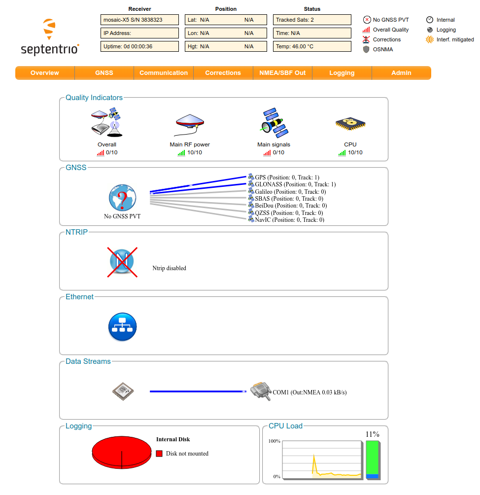
- 16160webadmin.jpg (126.5 KB ) - added by 5 months ago.
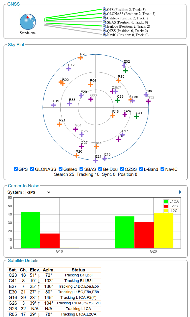
- 16160reception.jpg (111.5 KB ) - added by 5 months ago.
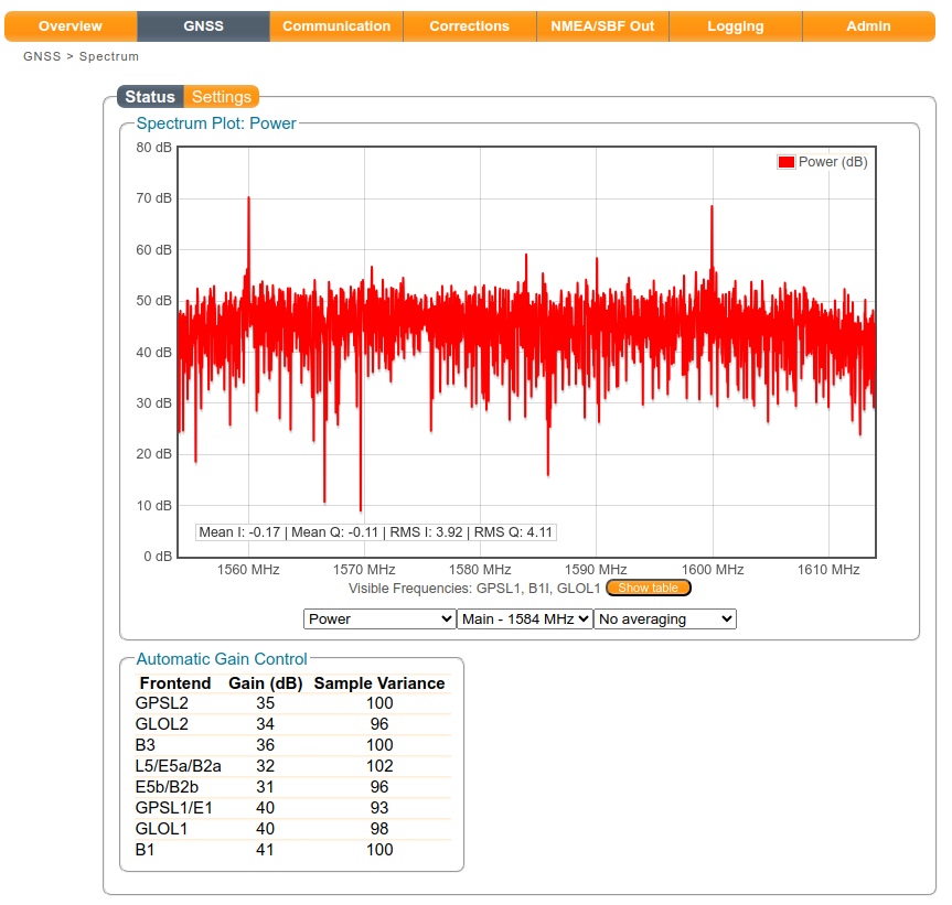
- 16160spectrum.jpg (101.8 KB ) - added by 5 months ago.
Download all attachments as: .zip