
Gateworks SoftPLC + SCADA Factory Automation Demo

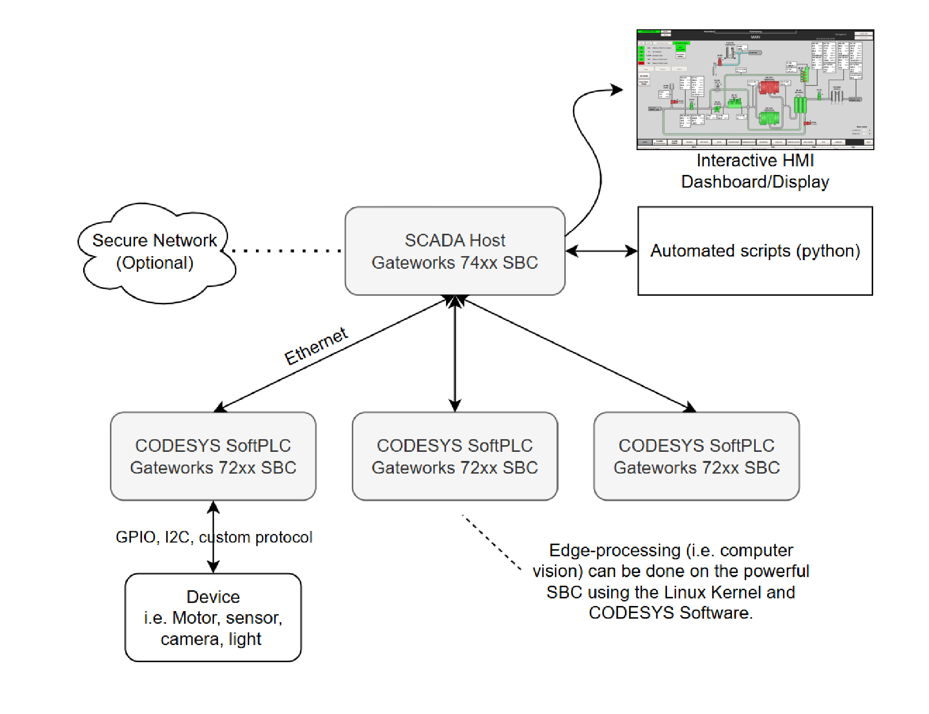
This documentation provides a technical overview + steps to create a SoftPLC device on a Gateworks SBC running custom user-defined ladder logic, then connect it over Modbus TCP to a SCADA controller for factory-automation environments. Gateworks SBCs provide a robust foundation for automation for smart-factories, and this guide shows how to use our SBCs as SoftPLCs and connect it both downwards to sensors and GPIO, and upwards via ethernet to SCADA and the cloud.

The CODESYS SoftPLC platform turns Gateworks SBCs into industrial-grade logic controllers for seamless, reliable factory automation at every level. CODESYS SoftPLCs are Linux-based and have more flexibility than traditional PLC controllers; Gateworks SBCs are the preferred industrial boards to host the CODESYS automation system.

CODESYS Ladder Logic
Ignition SCADA software can configure tasks and conditionals, and display comprehensive reliable dashboards for configuring and monitoring systems remotely or on-site. Acting as the “brain” of the system, it provides both oversight and configuration. Many users appreciate Python’s versatility, enabling scripts to trigger alarms or logic controllers for high-level automation. Given the critical task of overseeing automation, an unreliable computer is not an option. Hosting Ignition SCADA on a Gateworks board ensures reliability and robustness.

SCADA Dashboard
Hardware Requirements
For CODESYS SoftPLC:
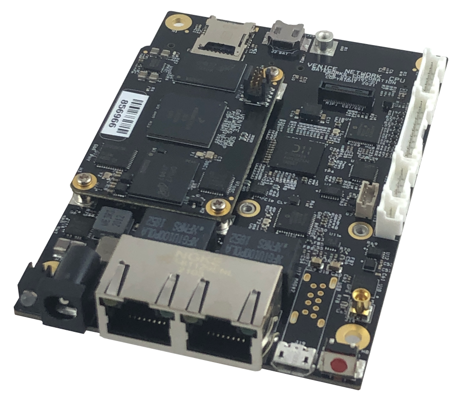
- 1x Gateworks SBC (Documentation uses GW7201)
- 2x Ethernet CAT.6 for network & POE
For Ignition SCADA:
- 1x Gateworks SBC (Recommended GW74xx for expansion capabilities)
- Ethernet CAT.6 for each directly connected PLC + POE
CODESYS Installation Steps
Installation occurs on the development host (Windows) and the Gateworks SBC (SoftPLC).
You will need:
- Fresh install of Ubuntu Noble Venice on a GW7xxx (this documentation was done with GW7201)
- CODESYS Development Environment on Windows Host
- A connection between host and SBC via IP (SSH connection steps here)
- CODESYS Control for Linux ARM SL, the runtime environment for the SoftPLC
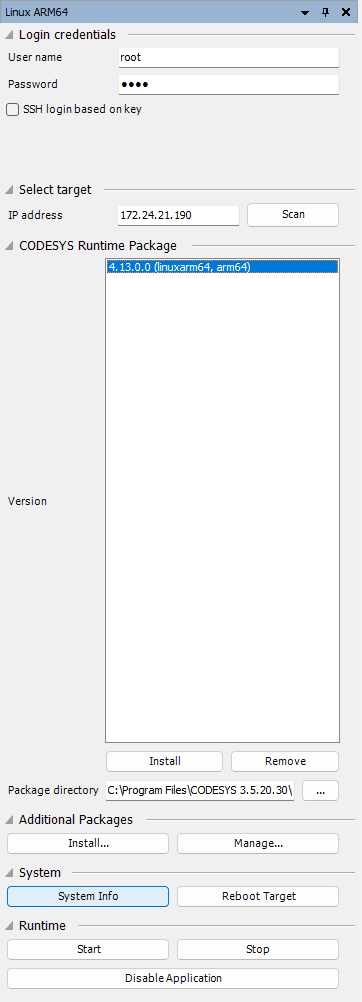
Once you have a confirmed connection/ping between the Windows machine and the board, install the CODESYS Linux Runtime which can be obtained in the link above. To install on the board, use the Windows host with CODESYS software which handles downloading. Create a new Standard Project.

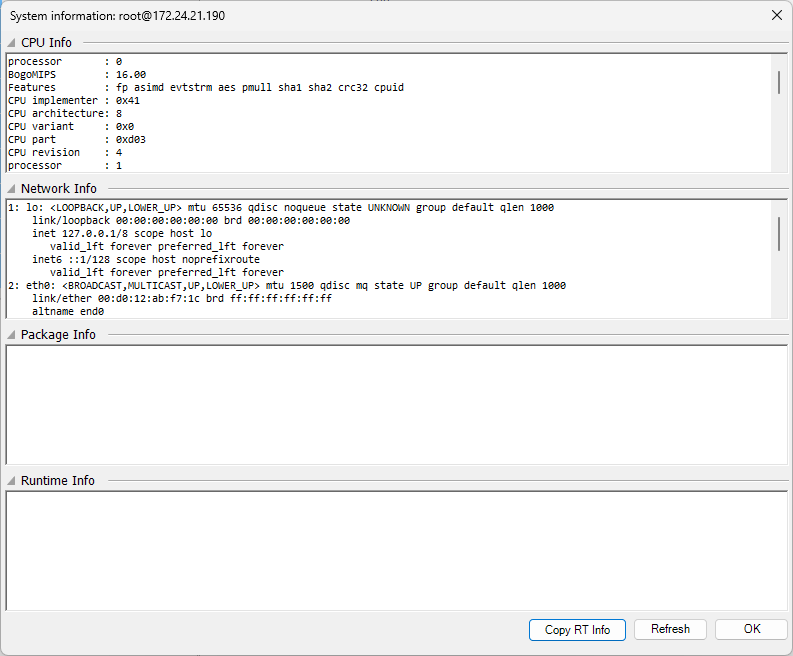
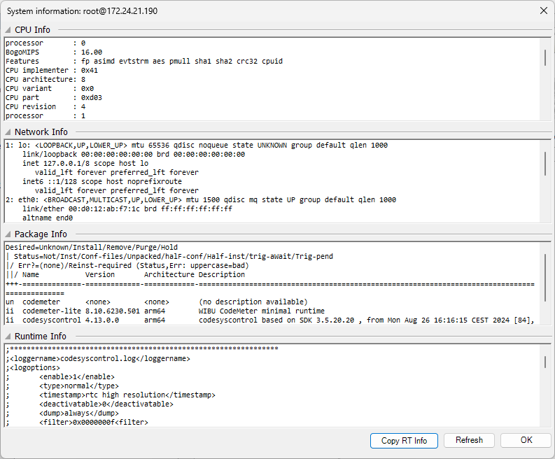
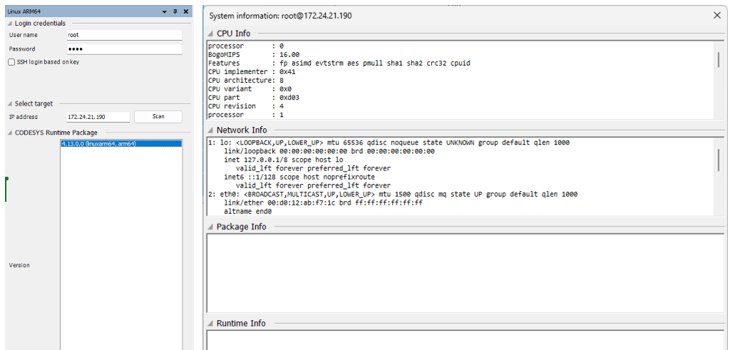
From a fresh install, make sure that you can ssh into the SBC root. Edit the sshd_config on the board if necessary. Then you should be able to fetch “System Info” from the Windows host given the username, password, and SBC IP.

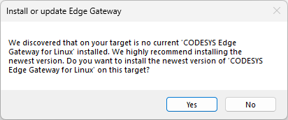
The CPU Info and Network Info areas being populated show that CODESYS can connect to the device. The next step is to install the CODESYS Runtime Package. This documentation assumes access to the 4.13.0.0 (linuxarm64, arm64) runtime package, listed above in the requirements, which can be accessed through the CODESYS website. Installing the runtime package will likely also prompt installation of the Edge Gateway, which also needs to be installed.

Once complete, click “Reboot Target” to ensure the device is running correctly. “System Info” will now show information about the package and runtime info.

The installation of the CODESYS runtime is now complete, and the SoftPLC is ready to have logic implemented on it. The next steps will show exactly how to do so.
Connecting to the PLC from CODESYS
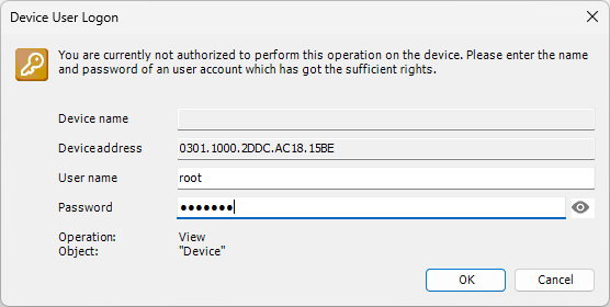
Now that the runtime and gateway are installed on the device, there is a second layer of abstraction when connecting to it from our Windows (development) host. There is the Linux user (in our case, the default “root”) and the SoftPLC Device user (which is determined on the first login). You will be prompted to create a device user when connecting to the device on the “Device” tab. Enter the IP address of the device/board on the right, and a connection will be established to that inner abstraction layer (The SoftPLC). You will be prompted to log in to the device.


Once connected, you will have a dashboard of the current program running on the PLC.
Ladder Diagrams + GPIO: Button to LED
We will implement a simple program through ladder logic in CodeSYS to turn on a light as long as a button is pressed. Infinitely more logic can be added, but the simple demo shows the connection between software and hardware; in the next section, we will include multi-device communication to reliably turn on and off lights.
Our GW7201 which this documentation is written on has 2 exposed GPIO ports by default. In most cases, GPIO ports will be exposed through expanders or other devices, and the same process should follow. You can find specific information on the Wiki about Gateworks GPIO and about Venice family DIO for your board specifically.
Our logic will use one DIO as an input (button), and one DIO as an output (LED).
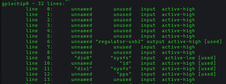
Running “$ gpioinfo gpiochip0” shows the DIO lines on the standalone SBC. In our case, they exist on Line 9 (dio0) and Line 11 (dio1)

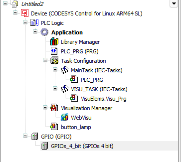
Add Device GPIO, Add device GPIO 4 pins (choice of 1, 4, or 16. We’re using 2, so selecting 4 will be the least complicated)

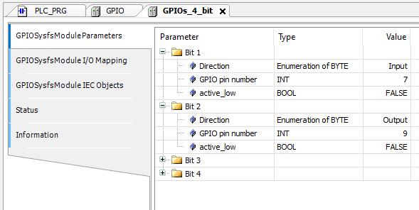
In the GPIOs_4_bit GPIOSysfsModuleParameters, establish a connection between Bits 1 and 2 and the DIOs listed from the gpioinfo response from earlier. In our case, DIO0 and DIO1 are on lines 9 and 11, but this varies from board to board (such as a GW7200 versus a GW7400). In this example, Bit 1 is an INPUT for the button, and Bit 2 is an OUTPUT for the LED.

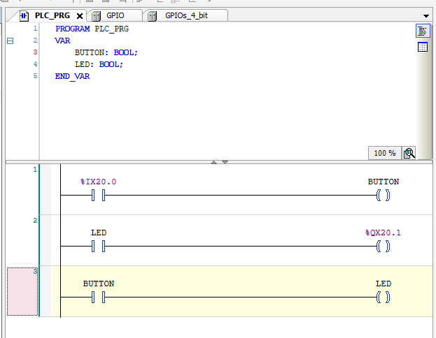
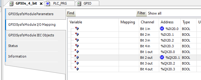
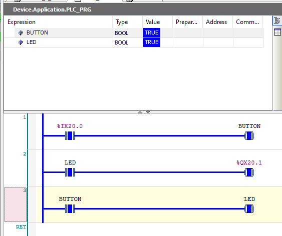
Once entered, view the CODESYS variables associated with each bit on the next tab labeled “GPIOSysfsModule I/O Mapping” (Bit 1 is an input, Bit 2 is an output)

On the ladder diagram PLC_PRG, connect the Bit 1 Input to BUTTON coil, and the LED variable to the Bit 2 output. The specific mapping name (i.e. %IX20.0) will change depending on your project. On the bottom network, we implement a simple connection directly between the BUTTON contact and the LED being activated.

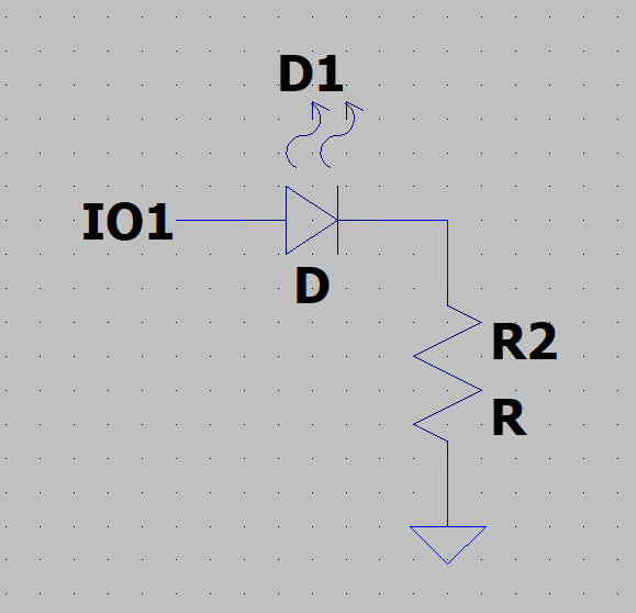
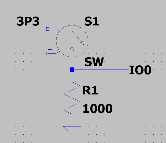
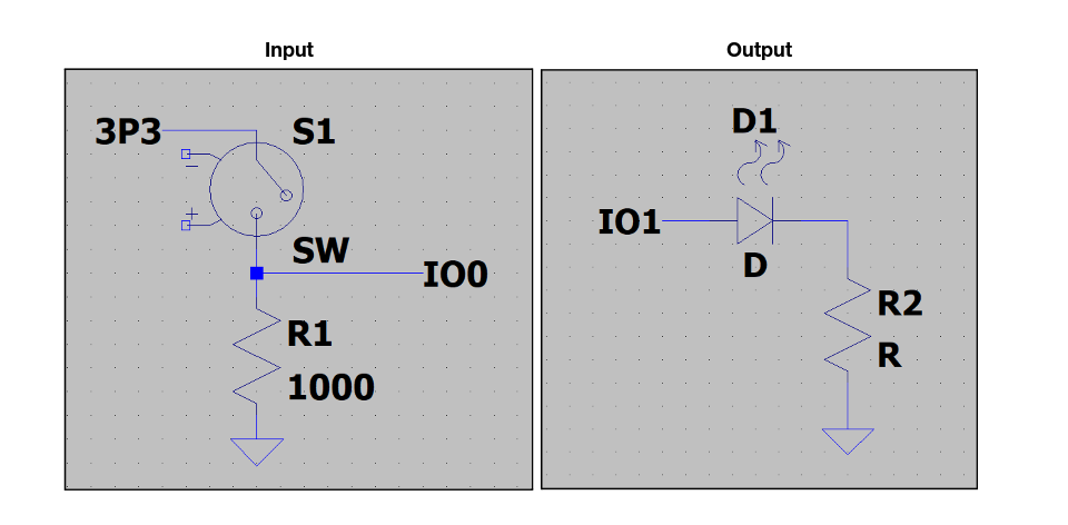
On a breadboard, establish a simple button connection using a pull-down resistor, pushbutton, and LED.

After the connections have been made, upload the program with the “login” button and watch as CODESYS shows a real-time view of the connections.

More customization can be done on the CODESYS application side, such as visualizations, which are easy to implement once you have the base logic set up successfully.

Modbus TCP Communication
Modbus TCP and Profinet are both communication protocols used in factory automation: Profinet by Siemens is a gold standard that Gateworks devices support. While Gateworks SBCs & CODESYS support Profinet just fine, Modbus TCP was used for this demo since Inductive Automation supports it natively.
Interfacing Modbus TCP In CODESYS
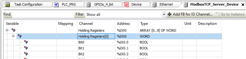
Add an Ethernet device to the Device, and then add a Modbus TCP Server Device to that ethernet device. This enables Modbus TCP communication on the SoftPLC. Configure the Ethernet device to have the IP of the SBC (static is preferred) In the Modbus TCP server device, note the bits from the preferred holding registers.

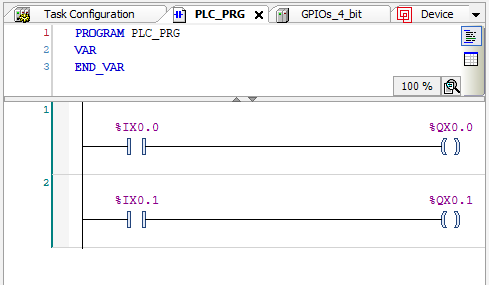
The Modbus TCP protocol opens up many read/write registers each containing 16 bits; these can be connected directly on the ladder logic diagram to remotely control them with commands or Ignition SCADA. In this case, the first 2 bits of register 0 are connected to the first 2 GPIOs (configured as output). This allows for commands to be sent to instantly control both LEDs independently.

Now you can upload the program to the PLC and test the functionality using the ‘mbpoll’ tool from the development machine’s command line.
Reading from Modbus TCP remotely using mbpoll
mbpoll -t 4 -c 2 -v <ip>
Writing to Modbus TCP (development only)
mbpoll -t 4 -v <ip> -r <register> <register value> mbpoll -t 4 -v <ip> [register values …
Connection to Ignition SCADA
Ignition SCADA is perfectly equipped to use Modbus TCP to robustly talk to a multitude of SoftPLCs; this is industry standard. Ignition has this process well documented here. The ladder logic diagrams we implemented earlier run independently of SCADA, and Modbus TCP’s registers serve as the interface between the SCADA “brain” overseeing automation and the PLCs.
Ensuring Security and Reliability
During the development process, we opened up the root of the Linux SBCs to SSH connections. This should be disabled in any production environment. VLAN isolation should also be used in production environments to protect the SBCs from outside traffic. In the production environment, the SBCs only communicate to the SCADA host via the MODBUS TCP protocol; all others should be blocked. Include layers of communication in the VLAN and strictly block all traffic between the PLC and outside devices. Gateworks SBCs run Linux, which has many resources for standardized, industrial networking.
Conclusion
With knowledge of implementing SoftPLCs and SCADA systems, you are now fully equipped with the foundation to implement robust, industrial-grade automation systems on Gateworks SBCs!
Attachments (27)
-
SCADA-PLC-GW.jpg
(580.4 KB
) - added by 17 months ago.
Automation system overview
-
ladder-logic-diagram-help-codesys-v0-dov1m4j4vi8d1.png
(576.9 KB
) - added by 17 months ago.
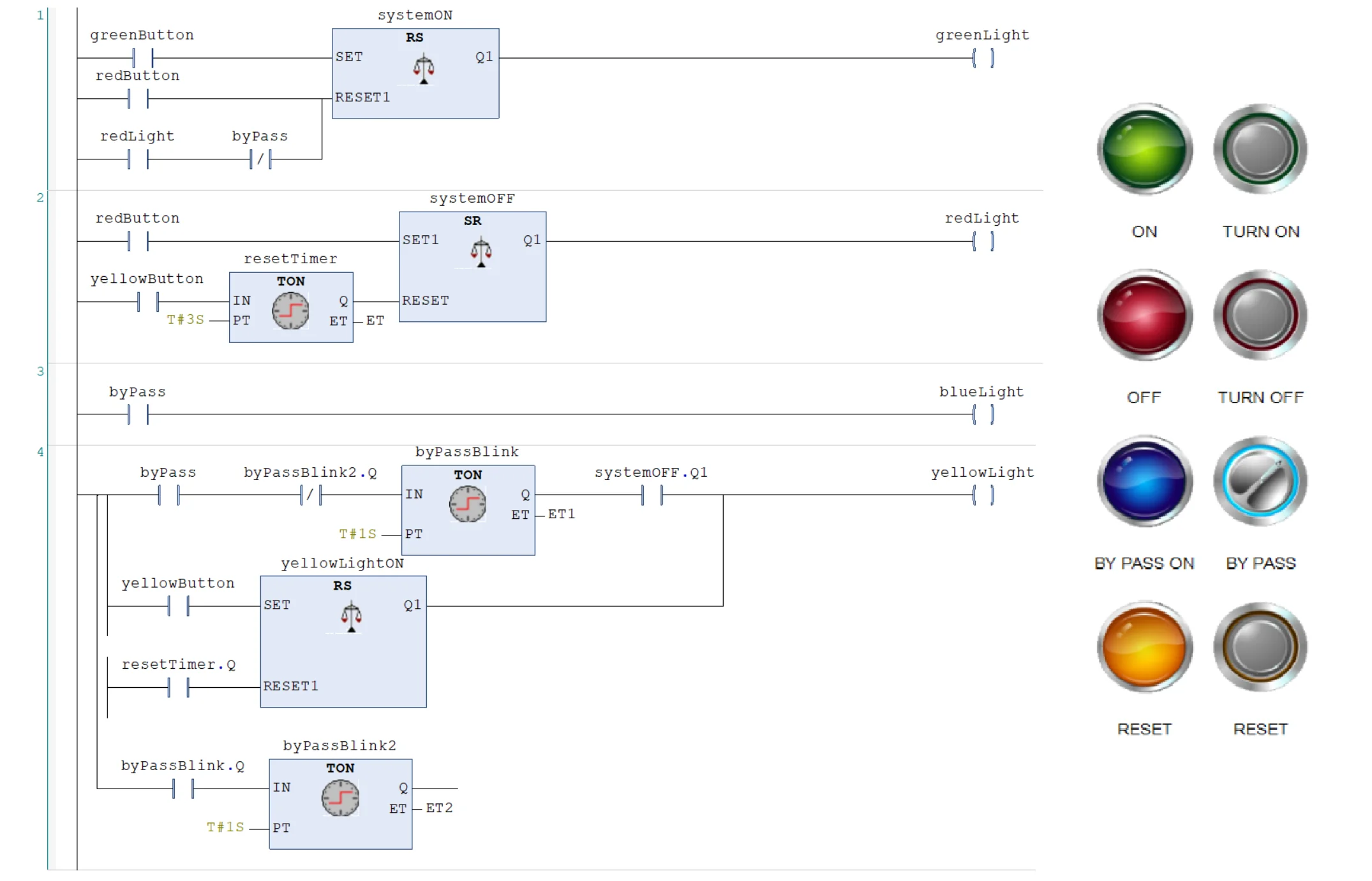
Ladder Logic
- scada_dash.jpg (83.5 KB ) - added by 17 months ago.
- image2.png (15.0 KB ) - added by 17 months ago.
- image3.png (11.0 KB ) - added by 17 months ago.
- image4.png (12.1 KB ) - added by 17 months ago.
- image7.png (114.6 KB ) - added by 17 months ago.
- image8.png (29.8 KB ) - added by 17 months ago.
- image8.2.png (29.8 KB ) - added by 17 months ago.
- image9.png (8.2 KB ) - added by 17 months ago.
- image10.png (18.5 KB ) - added by 17 months ago.
- image11.png (13.9 KB ) - added by 17 months ago.
- image11.2.png (13.9 KB ) - added by 17 months ago.
- image12.png (22.3 KB ) - added by 17 months ago.
- image13.png (20.5 KB ) - added by 17 months ago.
- image14.png (37.0 KB ) - added by 17 months ago.
- image15.png (7.6 KB ) - added by 17 months ago.
- image16.png (10.8 KB ) - added by 17 months ago.
- image17.png (48.3 KB ) - added by 17 months ago.
- image18.png (23.2 KB ) - added by 17 months ago.
- image19.png (17.1 KB ) - added by 17 months ago.
- image20.png (12.5 KB ) - added by 17 months ago.
- image21.png (19.0 KB ) - added by 17 months ago.
- compound.png (112.3 KB ) - added by 17 months ago.
- schematic.png (49.6 KB ) - added by 17 months ago.
- gw7200angle.png (878.9 KB ) - added by 17 months ago.
- factory_automation.png (1.2 MB ) - added by 17 months ago.
Download all attachments as: .zip