
| Version 94 (modified by , 3 years ago) ( diff ) |
|---|
-
802.11 WiFi
- Common Wireless Radio Hardware
- WiFi 6 & 802.11ax Radios
- W_DISABLE# pin (MiniPCIe and M.2 Sockets)
- Gateworks WiFi BSP Support
- Wireless Configuration (Standard Linux)
- Monitor Mode
- Mesh Point
- Linux Kernel Drivers
- Wireless Testing
- Tips for Improving AP Performance
- Where should I position my AP
- Which Wi-Fi Channel is Best
- WiFi Terminology and Concepts
- Doodle Labs WiFi Radios (Details)
- Validated USB radios from Amazon
This information has been tested and created for use on the Gateworks Single Board Computers (SBCs).
Gateworks SBCs can be viewed at the following link: http://www.gateworks.com

For information on various wireless technologies see the following pages:
802.11 WiFi
Gateworks has had extensive experience with wireless radio's. This list includes miniPCI and miniPCIe, specifically with the Atheros wireless chipsets which happen to be one of the most common chipset's used under Linux in the industrial world.
Out of box, our BSP's include the latest wireless drivers available. This allows our customers to get the latest and greatest support right away.

Common Wireless Radio Hardware
Gateworks re-sells some of the more popular radios in our on-line store and has tested several others. Please see the sections below for more information.
Wallys
The following radios have been tested on Gateworks SBCs:a
- Wallys DR900VX
- 3x3 MIMO
- QCA9880 chipset
- Gateworks GW17049
- Gateworks Shop Link
- Wallys DR600VX
- 2x2 MIMO
- QCA9880 chipset
- Gateworks GW17051
- Gateworks Shop Link
Compex
- Compex - High powered WiFi radios http://www.compex.com.sg/
- MiniPCIe Compex WLE900VX 7AA
- Gateworks sells this radio as a GW17032 - Gateworks Shop Site
- Pre-Certified with FCC
- 802.11b/g/n/a/ac
- ath10k
- dual-band: 2.4, 5
- 3x3 MIMO
- Testing Results
- Datasheet
- MiniPCIe Compex WLE900N5
- 802.11ac
- single-band: 5
- 3x3 MIMO
- MiniPCIe Compex WLE1216V5-20 - Highest Throughput
- 802.11a/n/ac Wave2
- ath10k
- 4x4 MU-MIMO
- 4 spatial streams (4SS) at 80MHz
- 2 spatial streams (2SS) at 80+80MHz (unclear if this is supported by driver/firmware/hostapd yet)
- Note that this card does not support VHT160 even though its EEPROM states it does
- Single-band: 5
- Tested on Newport GW630x with 4.14 kernel:
- Requires updated board-2.bin file from CT in
/lib/firmware/ath10k/QCA9984/hw1.0/board-2.bin
- Requires updated board-2.bin file from CT in
- Datasheet
- Compex Website
- Note that if W_DISABLE# is driven low to disable RF this card will not enumerate on the PCIe bus: see gpio/w_disable# for more details
- MiniPCIe Compex WLE900VX 7AA
Unex
- Unex - High powered WiFi radios http://www.unex.com.tw/wi-fi
- MiniPCIe Unex DAXA-O1
- 802.11a/n/ac
- ath10k
- dual-band: 2.4, 5
- 3x3 MIMO
- Datasheet
- MiniPCIe Unex DAXA-O1
Laird
Find all Laird Sterling (LWB5+) on-board wireless information on this dedicated wiki page: expansion/on-board-wireless
Intel
- MiniPCIe Intel 7260
- 802.11 ac/a/b/g/n
- Using Intel iwlwifi Driver
- dual-band: 2.4, 5
- 2x2 MIMO
- Other Specifications
- Note: This card cannot emit radiation in the 5GHz range, i.e. AP mode does not work in 5GHz
Silex
- MiniPCIe (Several Models) https://www.silextechnology.com/connectivity-solutions/embedded-wireless
- 802.11 ac/a/b/g/n and 802.11 a/b/g/n models
- Using ath10k and ath9k
- Dual-band: 2.4, 5
- 3x3 and 2x2 MIMO
- Industrial temperature version available
Sparklan
- MiniPCIe (Several Models) http://sparklan.com/p2-products.php?Class1=f041Z700QY1X2vGkyNcNQapMQBipkhEa9NBZ3fwn&PCIE
- 802.11 ac/a/b/g/n and 802.11 a/b/g/n models
- Using ath10k and ath9k
- Dual-band: 2.4, 5
- 3x3 and 2x2 MIMO
- Several models w/Bluetooth
- USB only model http://sparklan.com/p2-products-detail.php?PKey=955cc6uQPOo7CqIQegGjFPaAYOI5vS83LaQnGpl2-Mo&WPEQ-160ACN(BT)
Doodle Labs
- Doodle Labs - High powered WiFi radios http://doodlelabs.com/
- MiniPCIe Doodle Labs ACE-DB-3 Radio
- 802.11a/b/g/n/ac
- tri-band: 2.4, 5, 4.9
- 3x3 MIMO
- Datasheet
- MiniPCIe Doodle Labs ACE-DB-3 Radio
- Read more about Doodle Labs radios in the Doodle Labs Radio section below
WiFi 6 & 802.11ax Radios
WiFi6 & WiFi6E & 802.11ax is the latest, fastest generation of WiFi radios. These are bleeding edge and often require the latest software (kernel 5.15 or newer), firmware, and latest hardware.
WiFi6E is the 'extension' of WiFi6. Wi-Fi 6E supports 6-GHz. WiFi6 is backwards compatible with other previous WiFi versions, but WiFi6E is not.
Because the below radios are bleeding edge, the Linux kernel may still be working to add full support.
WiFi 6 / 802.11ax Radios Gateworks has seen on the market:
- Intel AX200 802.11ax 2x2 Intel (Gateworks tested on Ubuntu 5.15 kernel)
- Wallystech DR915 802.11ax 2x2 MediaTek
- EmWicon WMX7406-3TX 802.11ax 3x3 QCA (Qualcomm)
- Compex WLE3000H5-7A 802.11ax 4x4 QCA (Qualcomm)
WiFi 6E:
- Silex SX-PCEAX 802.11ax 2x2 QCA (Qualcomm QCA2066)
- Preliminary testing shows it is likely that a 6.1 or newer kernel is required & a signed board-2.bin file needs to be placed in the /lib/firmware/ath11k/WCN6855/hw2.1 folder on a running target. This would be using the ath11k open source driver. Silex however recommends using Qualcomm’s LEA driver built using Silex's instructional PDF.
- While it supports 2.4GHz, 5.8GHz and 6GHz, you can only select two active frequency at once. For example, 2.4GHz and 6GHz etc. The AP feature is a soft AP so it can support up to 32 clients.
- Please contact Silex for more support
W_DISABLE# pin (MiniPCIe and M.2 Sockets)
Note that MiniPCIe and M.2 sockets have 'W_DISABLE#' pins that are intended to disable all RF transmission on a wireless device.
Typically these signals are either driven high by default or pulled up with a pull-up resistor on-card and thus only need to be manipulated if you want to disable RF.
See gpio/w_disable# for more details
Gateworks WiFi BSP Support
Gateworks supports multiple Board Support Packages. The following table shows details on WiFi support for each:
| BSP | Product Families | Drivers | Modes |
|---|---|---|---|
| OpenWrt | All | ath5k/ath9k/ath10k | AP / client |
| Yocto | Ventana | ath5k/ath9k/ath10k | AP / client |
| Android | Ventana | ath5k/ath9k | AP / client |
| ubuntu | Ventana, Newport | ath9k/ath10k | AP / client |
If you are looking for additional support please contact support@…
OpenWrt Wireless Configuration
OpenWrt uses the standard Linux wireless utilities but configured and launched through its own configuration system.
For more info on configuring Wireless for OpenWrt see:
Yocto Wireless Configuration
Yocto uses the standard Linux utilities, init scripts, and conf files.
For more info on configuring Wireless for Yocto see:
Android Wireless Configuration
Android uses the standard Linux utilities but wraps them around a Network Daemon that performs configuration and management.
For more info on configuring Wireless for Android see:
Ubuntu Wireless Configuration
Ubuntu uses the standard Linux utilities, init scripts, and conf files.
For more info on configuring Wireless for Ubuntu see:
Wireless Configuration (Standard Linux)
There are several tools and applications that are used by Linux to configure wireless devices:
- iw
- hostapd
- wpa_supplicant
For more info on configuring Wireless for Yocto see:
iw (generic configuratoin)
The 'iw' tool is the modern tool (which replaces the older set of WIRELESS_EXTENSION tools such as iwconfig, iwpriv, iwlist, etc) for configuration of wireless drivers.
The full documentation is here but some common commands we find useful are:
- list devices:
iw dev ;# 'iw dev wlan0 info' for each dev
iw phy ;# 'iw phy phy0 info' for each dev
- list device info:
iw dev wlan0 info ;# basic info: ifname, mode, mac (same as iw wlan0 info)
iw phy phy0 info ;# detailed info: antennas, supported modes, bands, freqs (same as iw phy0 info)
iw dev wlan0 link # info about link
- antenna info:
iw phy phy0 | grep Antenna ;# get Antenna bitmasks
iw phy phy0 set antenna_gain <gainindbm>
iw phy phy0 set antenna <bitmap> | all <txbitmap> <rxbitmap> ;# set allowed antennas
- TX power info:
iw dev wlan0 set txpower <auto|fixed|limit> [<txpowermbm>]
iw phy phy0 set txpower <auto|fixed|limit> [<txpowermbm>]
iw phy phy0 set distance <distance meters> ;# set appropriate coverage class (0-114750)
iw phy phy0 set coverage <coverage class> ;# set coverage class (1 for every 3us of air prop time 0-255)
- channel:
iw phy phy0 channels #show available channels
iw dev wlan0 set channel <channel> [HT20|HT40+|HT40-]  ;# or iw phy
iw dev wlan0 set freq <freq> [HT20|HT40+|HT40-]  ;# or iw phy
iw dev wlan0 set freq <control freq> [20|40|80|80+80|160] [<center freq>] [<center freq2>]
iw phy phy0 set freq <freq> [HT20|HT40+|HT40-]
- 4-addr header parsing (WDS):
iw dev wlan0 set 4addr <on|off>
- interface mode:
iw dev wlan0 set type <managed|ibss|monitor|mesh|wds>
- rate masks (when fixed mask set you won't see T,p,P change in rc_stats but will see the stats change)
iw dev set bitrates ;# clear masks
iw dev wlan0 set bitrates ht-mcs-5 19 ;# set MCS-19
- interface creation:
iw phy phy0 interface add <name> type <type>
iw phy phy0 interface add mon0 type monitor
iw dev <name> del ;# delete interface
- turn off powersave mode:
# May increase wireless performance depending on radio
iw dev wlan0 set power_save off
Notes:
- most commands allow specification of a network device (ie wlan0) or a phy (ie phy0)
- most 'set' commands will show current settings if a value isn't specified
- 'iw wlan0 ...' is short for 'iw dev wlan0 ...' and 'iw phy0 ...' is short for 'iw phy phy0 ...'
References:
- http://wireless.kernel.org/en/users/Documentation/iw
- source:
- release tarballs: https://www.kernel.org/pub/software/network/iw/
- git http://git.kernel.org/cgit/linux/kernel/git/jberg/iw.git (tagged per kernel release)
hostapd (Access Point)
The hostapd application is the userspace application that configures and manages wireless drivers in Access Point (AP) mode.
References:
- http://hostap.epitest.fi/hostapd/
- http://wireless.kernel.org/en/users/Documentation/hostapd
- source:
- stable release tarballs: http://w1.fi/hostapd/
- git http://w1.fi/cgit/hostap/ (cgit: http://hostap.epitest.fi/cgit/hostap/)
Access Point Configuration (AP)
By default the Yocto BSP is configured to enable a Wireless Access Point.
The 'hostap-daemon' package provides the hostapd application which configures the radio for AP mode using configuration from /etc/hostapd.conf.
You will need to configure /etc/hostapd.conf to specify important details such as:
- interface
- driver type (the default is nl80211 which is used for all modern mac80211 drivers)
- bridge config
- ssid
- channel
- encryption
The default /etc/hostapd.conf file contains detailed documentation and you can find more info here. However, because every wireless cards' capabilities are vastly different from one another, Gateworks has written a script to help ascertain a proper hostapd.conf file. Though not 100% of the functionality mentioned in the hostapd documentation is supported, it does help the user create a hostapd.conf file specific to their wireless card.
This bash script, named hostapd-conf, is included in our latest Yocto 1.8/Master branches. To read over the script, please click here.
Usage is as follows:
root@ventana:~# ./hostapd-conf
hostapd-conf [OPTIONS] <iface> <ssid> <channel> [<htmode>] [<passphrase>]

Options:
 --help           - This help
 --br-name <name> - Name of bridge
 --wds <0|1>      - Enable WDS
 --version        - Print this version: v1.0

Example:
 Print channel information for wlan0 and exit:
  hostapd-conf wlan0

 State wlan0 SSID is 'myssid', on channel 6 with WPA2 passphrase "nowayinside":
  hostapd-conf wlan0 myssid 6 nowayinside

 State wlan0 is in named bridge br0, enable WDS, SSID 'myssid', channel 6,
 in HT20(802.11n), with WPA2 passphrase "nowayinside":
  hostapd-conf --br-name=br0 --wds=1 wlan0 myssid 6 HT20 nowayinside
Below are some usage cases for this script. In these examples, a WLE900VX radio was used. Note, any information that isn't apparent in the below script may be found via the iw phy phy<n> info command.
Step 1 : Scan Available Options
To view all channels/frequencies and HT modes that can emit radiation on a specified interface, indicate just the interface:
root@ventana:~# ./hostapd-conf wlan0
ERROR: SSID is empty

Available Channel Information on phy0
=====================================
Band 1:
Channel  Freq  Allowed HT Modes
0        0000  HT20 HT40 HT40+ HT40-
1        2412  HT20 HT40 HT40+
2        2417  HT20 HT40 HT40+
3        2422  HT20 HT40 HT40+
4        2427  HT20 HT40 HT40+
5        2432  HT20 HT40 HT40+ HT40-
6        2437  HT20 HT40 HT40+ HT40-
7        2442  HT20 HT40 HT40+ HT40-
8        2447  HT20 HT40 HT40+ HT40-
9        2452  HT20 HT40 HT40+ HT40-
10       2457  HT20 HT40 HT40-
11       2462  HT20 HT40 HT40-

Band 2:
Channel  Freq  Allowed HT Modes
0        0000  HT20 HT40 HT40+ HT40- VHT20 VHT40 VHT80
36       5180  HT20 HT40 HT40+ VHT20 VHT40 VHT80
40       5200  HT20 HT40 HT40- VHT20 VHT40 VHT80
44       5220  HT20 HT40 HT40+ VHT20 VHT40 VHT80
48       5240  HT20 HT40 HT40- VHT20 VHT40 VHT80
149      5745  HT20 HT40 HT40+ VHT20 VHT40 VHT80
153      5765  HT20 HT40 HT40- VHT20 VHT40 VHT80
157      5785  HT20 HT40 HT40+ VHT20 VHT40 VHT80
161      5805  HT20 HT40 HT40- VHT20 VHT40 VHT80
165      5825  HT20 HT40 HT40+ VHT20 VHT40 VHT80
Step 2 : Configure Access Point
2.4GHz 802.11g
To create a hostapd.conf file in the 2.4GHz range, using 802.11g technology:
root@ventana:~# ./hostapd-conf wlan0 test-ssid 6
Settings:
 IFACE:   wlan0
 PHY:     phy0
 SSID:    test-ssid
 CHANNEL: 6
 FREQ:    2437
 BANDS:   1 2
 HWMODE:  g

Written to hostapd-phy0.conf
root@ventana:~# cat hostapd-phy0.conf
# For more options, please visit the following:
#  http://linuxwireless.org/en/users/Documentation/hostapd/
driver=nl80211
logger_syslog=-1
logger_syslog_level=2
logger_stdout=-1
logger_stdout_level=2
# a=5GHz, g=2.4GHz
hw_mode=g
# channel=0 turns on ACS survey
channel=6
# Please take the following into consideration:
# Country code (ISO/IEC 3166-1). Used to set regulatory domain.
# Set as needed to indicate country in which device is operating.
# This can limit available channels and transmit power.
#country_code=US
# Enable IEEE 802.11d. This advertises the country_code and the set of allowed
# channels and transmit power levels based on the regulatory limits. The
# country_code setting must be configured with the correct country for
# IEEE 802.11d functions.
# (default: 0 = disabled)
#ieee80211d=1
# Enable IEEE 802.11h. This enables radar detection and DFS support if
# available. DFS support is required on outdoor 5 GHz channels in most countries
# of the world. This can be used only with ieee80211d=1.
# (default: 0 = disabled)
#ieee80211h=1
interface=wlan0
ctrl_interface=/var/run/hostapd
ctrl_interface_group=0
disassoc_low_ack=1
preamble=1
wmm_enabled=1
macaddr_acl=0
auth_algs=1
ignore_broadcast_ssid=0
ssid=test-ssid
ieee80211n=0
ieee80211ac=0
5.8GHz 802.11ac
To create a hostapd.conf file in the 5GHz range, using 802.11ac technology, plus WPA2 encryption:
root@ventana:~# ./hostapd-conf wlan0 test-ssid 157 VHT80 nowayinside
Settings:
 IFACE:      wlan0
 PHY:        phy0
 SSID:       test-ssid
 CHANNEL:    157
 FREQ:       5785
 BANDS:      1 2
 HWMODE:     a
 HTMODE:     VHT80
 PASSPHRASE: nowayinside

Written to hostapd-phy0.conf
root@ventana:~# cat hostapd-phy0.conf
# For more options, please visit the following:
#  http://linuxwireless.org/en/users/Documentation/hostapd/
driver=nl80211
logger_syslog=-1
logger_syslog_level=2
logger_stdout=-1
logger_stdout_level=2
# a=5GHz, g=2.4GHz
hw_mode=a
# channel=0 turns on ACS survey
channel=157
# Please take the following into consideration:
# Country code (ISO/IEC 3166-1). Used to set regulatory domain.
# Set as needed to indicate country in which device is operating.
# This can limit available channels and transmit power.
#country_code=US
# Enable IEEE 802.11d. This advertises the country_code and the set of allowed
# channels and transmit power levels based on the regulatory limits. The
# country_code setting must be configured with the correct country for
# IEEE 802.11d functions.
# (default: 0 = disabled)
#ieee80211d=1
# Enable IEEE 802.11h. This enables radar detection and DFS support if
# available. DFS support is required on outdoor 5 GHz channels in most countries
# of the world. This can be used only with ieee80211d=1.
# (default: 0 = disabled)
#ieee80211h=1
interface=wlan0
ctrl_interface=/var/run/hostapd
ctrl_interface_group=0
disassoc_low_ack=1
preamble=1
wmm_enabled=1
macaddr_acl=0
auth_algs=1
ignore_broadcast_ssid=0
# Put a 3 here if you want both WPA/WPA2
wpa=2
wpa_passphrase=nowayinside
wpa_key_mgmt=WPA-PSK
wpa_pairwise=TKIP
rsn_pairwise=CCMP
ssid=test-ssid
ieee80211n=1
ht_capab=[HT40+][LDPC][SHORT-GI-20][SHORT-GI-40][TX-STBC][RX-STBC1][DSSS_CCK-40]
ieee80211ac=1
vht_oper_chwidth=1
vht_oper_centr_freq_seg0_idx=155
vht_capab=[RXLDPC][SHORT-GI-80][TX-STBC-2BY1][RX-ANTENNA-PATTERN][TX-ANTENNA-PATTERN][RX-STBC1][MAX-MPDU-11454][MAX-A-MPDU-LEN-EXP7]
Step 3 : Copy Access Point Configuration
After the hostapd-<phy>.conf file has been created and any edits have been made (if any), you may either:
- Copy the
hostapd-phy.conffile over/etc/hostapd.confand restart hostapd, noting that/etc/network/interfacesisn't configuring the wlan interface automatically (e.g. make sure noauto wlan0exists in/etc/network/interfaces)mv /etc/hostapd.conf /etc/hostapd.conf.bak # Backup original hostapd.conf file cp hostapd-phy0.conf /etc/hostapd.conf /etc/init.d/hostapd restart - Run hostapd using this new conf file, knowing that the settings won't persist over a new boot:
root@ventana:~# /etc/init.d/hostapd stop
root@ventana:~# hostapd -B hostapd-phy0.conf
Configuration file: hostapd-phy0.conf
[ 1825.468968] IPv6: ADDRCONF(NETDEV_UP): wlan0: link is not ready
wlan0: interface state UNINITIALIZED->HT_SCAN
[ 1825.636135] IPv6: ADDRCONF(NETDEV_CHANGE): wlan0: link becomes ready
At this point your wlan0 interface should be up and authenticating with WiFi clients and the next step is to configure IP networking (below).
Routed Access Point
A routed Access Point is used when you want the wireless network to have its own DHCP server and network. In this case traffic is routed across the WAN (Wide Area Network) interface (ie eth0) and WLAN (Wireless Local Area Network) interface (ie wlan0). This is the typical configuration for a wireless access point.
For this you need:
- the WAN (Wide Area Network) interface (ie eth0) should have an IP configuration from the WAN segment from the upstream Internet provider
- the WLAN network interface (ie wlan0) should be assigned a static address on a private network
- A DHCP server (ie dnsmasq) configured to serve a private IP address range on the WLAN network interface (ie wlan0)
- Network Address Translation (NAT) routing configuration using Linux iptables and Linux kernel netfilter support
- ip forwarding enabled in kernel
Configuration:
- Update apt-get and install dnsmasq
apt-get update
apt-get install dnsmasq -y
- Kill systemd-resolved process to avoid conflict with dnsmasq
systemctl stop systemd-resolved
systemctl mask systemd-resolved
- Remove symlinked resolve.conf and recreate the file with your preferred nameserver
rm /etc/resolv.conf
echo nameserver 8.8.8.8 | tee /etc/resolv.conf
- configure your WAN and WLAN interfaces in /etc/network/interfaces. Here we will use eth0 as our WAN configured to obtain IP configuration via DHCP from the upstream provider and wlan0 as our WLAN configured with a DHCP server for a private subnet on the 10.0.0/24 network:
cat << EOF > /etc/network/interfaces
# WAN interface
auto eth0
iface eth0 inet dhcp

# WLAN interface
auto wlan0
iface wlan0 inet static
        address 10.0.0.1
        netmask 255.255.255.0

# NAT configuration via iptables
post-up iptables-restore < /etc/iptables.ipv4.nat
EOF
- Configure dnsmasq. Here we will configure it to serve addresses on the 10.0.0/24 network with a pool of 190 addresses from .10 to .200 with a 2hour lease:
cat << EOF > /etc/dnsmasq.conf
interface=wlan0
dhcp-range=10.0.0.10,10.0.0.200,2h
EOF
- Restart the dnsmasq service
systemctl restart dnsmasq
- Configure Linux NAT routing. We will do this for the current boot and use that configuration to store hooks for subsequent reboots:
# enable forwarding on bootup
echo net.ipv4.ip_forward=1 >> /etc/sysctl.conf

# Configure NAT via iptables and then save its config to the restore script
iptables -t nat -A POSTROUTING -o eth0 -j MASQUERADE
iptables -A FORWARD -i eth0 -o wlan0 -j ACCEPT
iptables -A FORWARD -i wlan0 -o eth0 -j ACCEPT
iptables-save > /etc/iptables.ipv4.nat
chmod +x /etc/iptables.ipv4.nat
- restart networking and enable forwarding (or sync and reboot at this point instead):
/etc/init.d/networking restart
echo 1 > /proc/sys/net/ipv4/ip_forward
- Kick off your AP
hostapd hostapd-phy1.conf &
Bridged Access Point
A bridged Access Point is used to provide an a Wireless Access Point on a LAN that already has a DHCP server and creates a bridge between the LAN interface and the WIFI interface such that wireless client DHCP requests will be bridged to the LAN and answered from there.
For this you need:
- udhcpc package
- bridge-utils package
- CONFIG_BRIDGE support in kernel (default in our Yocto kernel)
- ip forwarding enabled in kernel
- create a bridge between your wifi interface and your lan interface. For example, assuming wlan0 and eth0:
# create a bride and add interfaces to it
brctl addbr br0
brctl addif br0 eth0
brctl addif br0 wlan0
# bring it up
ifconfig br0 up
# use DHCP to assign IP info
udhcpc -i br0
- Note that you can use /etc/network/interfaces to bring up and configure the bridge, but if you are using a fairly limited ifup/ifdown (like busybox) you will probably need to create the bridge first (ie in an init script prior to networking coming up)
- enable IP forwarding:
echo 1 > /proc/sys/net/ipv4/ip_forward
- you can enable IP forwarding on bootup with:
echo net.ipv4.ip_forward=1 >> /etc/sysctl.conf
- you can enable IP forwarding on bootup with:
Note that if your intention is to also create a wireless client bridge where a wireless client connection is bridging its wireless to a local Ethernet network you will need to enable WDS/4-addr header parsing on both the Access Point and the Client. To do this on the Access Point, add the following to /etc/hostapd.conf:
wds_sta=1
Alternatively, if using the hostapd-conf script, an option exists to enable this feature via --wds=1.
Troubleshooting
If encountering bad TCP performance with MIMO cards (typically ath10k):
If encountering issues:
hostapd-confwas written for and takes advantage of the bash shell, make sure you aren't running it with another shell program (ie Ubuntu's default "dash" shell)- ensure both hostapd and wpa_supplicant are not both trying to manage the interface (ie you have it configured for both AP and Client mode)
- ensure your client can see the AP (ie
iw dev wlan0scan for a Linux client, or use a wireless scanner such as 'Wifi Analyzer' on an Android device) - For client mode ensure the kernel shows that you are associated with the AP. You should see
wlan0: associatedin the kernel messages - check your encryption settings
- if you can ping between the AP and the client directly but not get through them:
- check your routing configuration (ie via
route -non Linux) and make sure you have a proper gateway - if trying to bridge wireless to ethernet networks ensure 'both' the AP and the Client have 4addr header parsing enabled
- check your routing configuration (ie via
- if DNS resolution is not occurring first make sure you can ping the nameserver by IP
wpa-supplicant (Client)
The wpa-supplicant application is the userspace application that configures and manages wireless drivers in Station (STA) mode.
References:
- http://hostap.epitest.fi/wpa_supplicant/
- http://wireless.kernel.org/en/users/Documentation/wpa_supplicant
- source:
- stable release tarballs: http://w1.fi/hostapd/
- git git://w1.fi/srv/git/hostap.git (cgit: http://hostap.epitest.fi/cgit/hostap/)
You generate a wpa_supplicant.conf file using a tool called wpa_passphrase:
~# wpa_passphrase MYSSID MYWPAPASSCODE
network={
        ssid="MYSSID"
        #psk="MYWPAPASSCODE"
        psk=82207641ae13124ee6dc8fd2642605ac52a17405263b0b3203ee5cdb826d700d
}
The following steps below can be used to connect to a WPA access point. You will likely need to alter this depending on your OS and distribution.
Step 1: Create wpa_supplicant.conf
For the following example we will use an SSID of 'MYSSID' and a WPA passcode of 'MYWPAPASSCODE' (replace with values your AP is configured with):
root@ventana:~# wpa_passphrase MYSSID MYWPAPASSCODE > /etc/wpa_supplicant.conf
Step 2: Start wpa_supplicant
To start wpa_supplicant manually:
killall wpa_supplicant # make sure its not already running
wpa_supplicant -i wlan0 -c /etc/wpa_supplicant.conf -B
Step 3: HDCP
To obtain DHCP network configuratnoi:
dhclient wlan0
Monitor Mode
Monitor all traffic on a wireless channel.
Check that your wireless interface supports monitor mode.
iw list |grep monitor
Check current mode.
iw dev
Configure radio (for example wlan0).
ip link set wlan0 down
iw wlan0 set monitor control
ip link set wlan0 up
Optional
Scan traffic using tshark (terminal wireshark).
apt-get install tshark
tshark -i wlan0
Mesh Point
To read more about mesh see our dedicated mesh page.
Linux Kernel Drivers
There are various linux kernel drivers such as madwifi, ath5k, ath9k, ath10k, iwlwifi, to name a few. The below few sections will talk at length about several of them.
As of 2018
- Ath5k: Most ath5k cards have been deprecated.
- Ath9k: Does not require special firmware for radios. Common & stable driver.
- Ath10k: Requires a special firmware that gets loaded on the radio. Latest driver for high speed AC cards.
Atheros AR5xxx 802.11abg cards (ath5k)
There are two driver options for the Atheros AR5xxx based 802.11abg cards:
- madwifi driver - development of this driver has ceased but it still has been known to outperform the fully opensource ath5k replacement and has some additional features that are not (and will not be) in ath5k
- ath5k - mac80211 driver - driver should be stable, but does not get much attention anymore as most users have moved on to 802.11n or 802.11ac devices
- see ath5k for more info
Theoretical max throughput rate of 802.11abg is 54mbps. Typical performance is around 30mbps (TCP)
Atheros AR9xxx 802.11abgn cards (ath9k)
The linux-wireless 'ath9k' driver supports the Atheros AR9xxx based 802.11n cads.
The 802.11n standard released in 2009 introduces some additions on top of the 802.11a standard:
- widening the channel bandwidth (up to 40MHz)
- Multiple Input(rx) Multiple Output(tx) streams (MIMO) up to 4
- 64-QAM modulation
Current popular hardware available supports up to 3x3 MIMO and up to 40MHz channel bandwidths using HT40+/HT40- which can 'theoretically yield' 300mbps of throughput. Actual results will vary based on CPU and bus bottlenecks, driver performance, and RF characteristics.
We regularly obtain throughputs around 150mbps.
See ath9k for more info
Atheros AR10xx 802.11ac cards (ath10k)
The linux-wireless 'ath10k' driver supports the Atheros AR10xx based 802.11ac cards.
The 802.11ac standard which was developed from 2011 through 2013 and approved in Jan 2014, introduces some additions on top of the 802.11n standards:
- Widening the channel bandwidth (up to 160MHz)
- Increased MIMO spatial streams (up to 8 vs 4 in 802.11n)
- Multi-user MIMO (aka MU-MIMO)
- High-density modulation (up to 256-QAM vs 64-QAM for 802.11n)
Current popular hardware available supports up to 4x4 MU-MIMO and up to 160MHz channel bandwidths using VHT160 which can theoretically yield >2.0gbps of throughput. Some cards also support VHT80+80 which functions similarly to VHT160 but is composed to two 80MHz channels that do not need to be contiguous, which can help with band selection. Actual results will vary based on CPU and bus bottlenecks, driver performance, and RF characteristics.
ath10k notes:
- 10.1.467.2-1
- What we ship with
- Focuses as AP in which DFS works. STA mode works, but not well tested. No AdHoc or P2P support
- Works in wireless bridge with upstream ath10k patches. These patches are in our 14.08 Branch (as well as trunk) of OpenWrt.
- 999.999.0.636
- Supports both AP and STA, AdHoc, and P2P. Has issues with DFS and cannot be configured an an AP in a wireless bridge
- Has less than half the performance than the 10.1.467.2-1 firmware. This was a primary reason for not choosing this firmware as our default shipped firmware.
- Monitor mode is not supported (crashes the firmware).
- TX Power inconsistent
Verifying / Checking Firmware Version
To check which version of ath10k firmware is being used on the Single board computer, use the dmesg and grep command:
root@OpenWrt:/# dmesg | grep ath10k
[   10.934967] ath10k: qca988x hw2.0 (0x4100016c, 0x043202ff) fw 10.1.467.2-1
root@OpenWrt:/#
Alternative Firmware instructions
To select between default and custom firmware you must rename or re-link it using the existing filenames in the driver directory. The driver will not use your custom firmware unless it has a name it's familiar with. This can vary depending on the chipset firmware you are intending to use as well as the BSP
Some examples:
- link CT's QCA988x firmware on OpenWrt 16.02:
$ cd /lib/firmware/ath10k/QCA988X/hw2.0/
$ ln -sf firmware-2-ct-full-community-beta.bin firmware-2.bin
$ # Reboot board
- Replace stock QCA9984 (to support Wave2 cards such as the WLE1216) firmware with CT's:
# Download Candelatech's firmware.bin and board.bin files
wget http://www.candelatech.com/downloads/ath10k-9984-10-4/board-2-ct.bin
wget http://www.candelatech.com/downloads/ath10k-9984-10-4/firmware-5-ct-full-community.bin

# Back up old files
cp /lib/firmware/ath10k/QCA9984/hw1.0/board-2.bin /lib/firmware/ath10k/QCA9984/hw1.0/board-2.bin_old
cp /lib/firmware/ath10k/QCA9984/hw1.0/firmware-5.bin /lib/firmware/ath10k/QCA9984/hw1.0/firmware-5.bin_old

# Drop in Candelatech files
mv board-2-ct.bin /lib/firmware/ath10k/QCA9984/hw1.0/board-2.bin
mv firmware-5-ct-full-community.bin /lib/firmware/ath10k/QCA9984/hw1.0/firmware-5.bin
That's it! You can use this method to link any firmware, so long as it's called firmware-2.bin (and if using the latest ath10k drivers, firmware-3.bin).
Candelatech
Candelatech licenses the source code for the ath0k firmware from QCA and has been actively developing it to provide enhancements and bugfixes that are not necessarily limitted to QCA's stock firmware priorities. One such enhancement is that they add IBSS/adhoc support.
Candelatech also has a web page for custom firmware files that may be required for certain radio's such as the WLE1216V5-20 wave 2 radio.
You may need this firmware if the ath10k driver and QCAXXXX firmware combination does not properly probe your device and create an interface. This would appear in your system log as:
root@xenial-newport:~# dmesg | grep ath10k
[    2.362523] ath10k_pci 0000:02:00.0: Direct firmware load for ath10k/QCA9984/hw1.0/board-pci-168c:003e:11ad:0804.bin failed with error -2
[    2.362527] ath10k_pci 0000:02:00.0: failed to load spec board file, falling back to generic: -2
[    2.362536] ath10k_pci 0000:02:00.0: Direct firmware load for ath10k/QCA9984/hw1.0/board.bin failed with error -2
[    2.362538] ath10k_pci 0000:02:00.0: failed to fetch generic board data: -2
[    2.362540] ath10k_pci 0000:02:00.0: failed to fetch board file: -2
[    2.362541] ath10k_pci 0000:02:00.0: could not fetch firmware files (-2)
[    2.362543] ath10k_pci 0000:02:00.0: could not probe fw (-2)
If this is the case, you can use CT's firmware as follows:
# Download Candelatech's firmware.bin and board.bin files
wget http://www.candelatech.com/downloads/ath10k-9984-10-4/board-2-ct.bin
wget http://www.candelatech.com/downloads/ath10k-9984-10-4/firmware-5-ct-full-community.bin

# Back up old files
cp /lib/firmware/ath10k/QCA9984/hw1.0/board-2.bin /lib/firmware/ath10k/QCA9984/hw1.0/board-2.bin_old
cp /lib/firmware/ath10k/QCA9984/hw1.0/firmware-5.bin /lib/firmware/ath10k/QCA9984/hw1.0/firmware-5.bin_old

# Drop in Candelatech files
mv board-2-ct.bin /lib/firmware/ath10k/QCA9984/hw1.0/board-2.bin
mv firmware-5-ct-full-community.bin /lib/firmware/ath10k/QCA9984/hw1.0/firmware-5.bin
- Note that this example was done for the WLE1216V5-20 wave 2 radio using a
QCA9984chipset. You may need to change yourwgetand/usr/lib/firmware/...targets accordingly. - Note that if you want to use the stock firmware you can just replace the board-2.bin file with CT's until the stock firmware supports the Wave2 cards properly.
Finally, to see what's current in ath10k, see here for more info
Atheros 802.11ax cards (ath11k)
Ath11k is a Linux driver for Qualcomm 802.11AX devices. 802.11ax is often called WiFi6.
Examples of Athh11k Radios:
- Compex WLE300H2
- Qualcomm QCN9024/9074 'Pine' series
- Emwicon WMX7406
- Qualcomm QCN9074
- 3x3 and 4x4 options available
Support was first added upstream in kernel version 5.6, though it's recommended to use a kernel 5.15 or newer. Gateworks has successfully tested on a Venice board using 5.15 kernel. Testing with a Ventana board on a 5.10 kernel was unsuccessful.
To enable support for this device in the kernel menuconfig enable the option for "CRYPTO_MICHAEL_MIC" then "ATH11K", instructions on kernel.org suggest this option should be enabled as a module, not static to the kernel.
Currently the firmware for Ath11k cards is not included in our prebuilt images. To add it:
- On your workstation download the latest firmware:
git clone git://git.kernel.org/pub/scm/linux/kernel/git/firmware/linux-firmware.git
- On your Gateworks SBC:
cd cd /lib/firmware/ath11k/
scp -r <hostname>@<ipaddress_of_workstation>:/<path_to_ath11k_firmware>/linux-firmware/ath11k/* .
sync
reboot
- Verify the interface is available using the command "ls /sys/class/net".
More CMA memory may need to be allocated.
In dmesg check for messages regarding inadequate CMA:
[    7.533137] cma: cma_alloc: reserved: alloc failed, req-size: 512 pages, ret: -12
[    7.541360] cma: cma_alloc: reserved: alloc failed, req-size: 512 pages, ret: -12
To remedy:
#in U-boot
setenv bootargs ${bootargs} cma=128M
saveenv
Speed testing was bottlenecked by the router being used. WLE3000H2 maxed out its throughput.
#iperf3 using 2 WLE3000H2's across Netgear Wifi6 AX1800 dual band WAP:


root@focal-venice:~# iperf3 -c 192.168.1.5
Connecting to host 192.168.1.5, port 5201
[  5] local 192.168.1.127 port 58128 connected to 192.168.1.5 port 5201
[ ID] Interval           Transfer     Bitrate         Retr  Cwnd
[  5]   0.00-1.00   sec  51.3 MBytes   430 Mbits/sec    0   2.11 MBytes
[  5]   1.00-2.00   sec  52.5 MBytes   440 Mbits/sec    0   2.76 MBytes
[  5]   2.00-3.00   sec  53.8 MBytes   451 Mbits/sec    0   3.08 MBytes
[  5]   3.00-4.00   sec  51.2 MBytes   430 Mbits/sec    0   3.08 MBytes
[  5]   4.00-5.00   sec  56.2 MBytes   472 Mbits/sec    0   3.08 MBytes
[  5]   5.00-6.00   sec  52.5 MBytes   440 Mbits/sec    0   3.08 MBytes
[  5]   6.00-7.00   sec  55.0 MBytes   461 Mbits/sec    0   3.08 MBytes
[  5]   7.00-8.00   sec  55.0 MBytes   462 Mbits/sec    0   3.08 MBytes
[  5]   8.00-9.00   sec  52.5 MBytes   440 Mbits/sec    0   3.08 MBytes
[  5]   9.00-10.00  sec  53.8 MBytes   451 Mbits/sec    0   3.08 MBytes
- - - - - - - - - - - - - - - - - - - - - - - - -
[ ID] Interval           Transfer     Bitrate         Retr
[  5]   0.00-10.00  sec   534 MBytes   448 Mbits/sec    0             sender
[  5]   0.00-10.01  sec   531 MBytes   445 Mbits/sec                  receiver
References:
https://wireless.wiki.kernel.org/en/users/drivers/ath11k
https://wireless.wiki.kernel.org/en/users/drivers/ath11k/installation
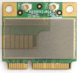
Intel 802.11AX cards (iwlwifi) AX200
Gateworks has recently validated Alfa AWPCIE-AX200U a cost effective (half size) mPCI-e form factor card. The AX200U supports WI-FI6 (IEEE 802.11AX) in 2.4 and 5ghz modes and has integrated BT5, it is also backward compatible with IEEE 802.11a/b/g/n/ac. This card uses both a PCI-e 1x lane and USB 2.0 for BT. The AX200 chipset this card is based on was developed by Intel. Intel reports a thermal rating from 0C to 80C. Please see the Intel ARK page for more details.
Linux support is provided by the iwlwifi driver, which is included in the mainline kernel source. The compatibility with Gateworks prebuilt Ubuntu images is plug and play. A limitation of this driver is AP's can only be hosted at 2.4GHZ. This driver does provide support for station (client) at 5ghz or 2.4ghz, P2P, Monitor, and IBSS. The chipset is also capable of packet injection which makes it an excellent option for use with the Aircrack-ng suite and Kali Linux which is available from Offensive Security for the Ventana and Newport platforms.
Special Notes
- This card doesn't seem well supported on a 5.4 kernel. Please use 5.10 or 5.15 or newer
- Note that depending on the OS you have, some hostapd-conf versions require a patch for this card such as below:
root@focal-venice:~# diff /usr/bin/hostapd-conf hostapd-conf
275c275
<                     | grep "Capabilities: " | cut -d" " -f2)
---
>                     | grep "Capabilities: 0x" | cut -d" " -f2)
The AX200 requires a firmware file that may or may not be on the board you are using:
Download the firmware here and place the iwlwifi-cc-a0-46.ucode in the /lib/firmware/ folder on the running system.
The AX200U is one of the fastest low cost wi-fi cards we have validated to date, below are the results of real world type iperf3 tests using a WI-FI6 capable Netgear (WAX204) wireless router.
Accepted connection from 192.168.1.3, port 46278
[  5] local 192.168.1.2 port 5201 connected to 192.168.1.3 port 46280
[ ID] Interval           Transfer     Bandwidth
[  5]   0.00-1.00   sec  52.6 MBytes   441 Mbits/sec
[  5]   1.00-2.00   sec  87.4 MBytes   733 Mbits/sec
[  5]   2.00-3.00   sec  89.7 MBytes   752 Mbits/sec
[  5]   3.00-4.00   sec  94.7 MBytes   795 Mbits/sec
[  5]   4.00-5.00   sec  92.6 MBytes   777 Mbits/sec
[  5]   5.00-6.00   sec  87.1 MBytes   731 Mbits/sec
[  5]   6.00-7.00   sec  86.0 MBytes   722 Mbits/sec
[  5]   7.00-8.00   sec  65.9 MBytes   552 Mbits/sec
[  5]   8.00-9.00   sec  79.4 MBytes   666 Mbits/sec
[  5]   9.00-10.00  sec  88.5 MBytes   742 Mbits/sec
[  5]  10.00-10.01  sec   954 KBytes   763 Mbits/sec
- - - - - - - - - - - - - - - - - - - - - - - - -
[ ID] Interval           Transfer     Bandwidth       Retr
[  5]   0.00-10.01  sec   826 MBytes   692 Mbits/sec    0             sender
[  5]   0.00-10.01  sec   825 MBytes   691 Mbits/sec                  receiver
Wireless Testing
First, some testing vocabulary:
Symbol Legend Key Meaning AP Access Point STA Station <---> Ethernet Connection <- -> Wireless Connection (S) iperf server (1) (C) iperf client (2) X Doesn't Work NA Didn't Test
1. TCP server run with: iperf -s -w3M; UDP server run with: iperf -su
2. TCP client run with: iperf -c $IP -i1 -t25 -w3M; UDP client run with: iperf -u -c $IP -i1 -t25 -b999M
- Infrastructure mode means the following:
1. Testing between AP and STA
(S)     (C)
AP<- ->STA

2. Testing between WAN and STA (Our standard infrastructure mode test)
(S)             (C)
PC-A<--->AP<- ->STA
- Wireless Bridging means the following:
(S)                     (C)
PC-A<--->AP<- ->STA<--->PC-B
- AdHoc means the following:
1. No Bridge
(S)       (C)
NODE1<- ->NODE2 (Our standard !AdHoc test)

2. With Bridge (Requires special software)
(S)                          (C)
PC-A<--->NODE1<- ->NODE2<--->PC-B
Below is an example setup of how we test and with what hardware:

1. 60dB Attenuators on each chain
2. Directional Coupler (Krytar 1850 shown)
3. Power Sensor (Agilent 8481A shown)
4. Power Meter (HP E4418A shown)
The image above shows our testing setup. In general, to test TX Power, we use a Power Meter + Power Sensor + Directional Coupler. Further, when people talk about performance, they typically are talking about throughput from AP<- ->STA. When we talk about performance, we spell out specifically which network topology we are testing, who is generating/sending packets, and who is receiving. This should make it very clear where performance numbers came from and how you can compare against them.
WLE900VX and Ubuntu
Troubleshooting:
- "apt-get install linux-firmware" package is crucial to making this card work.
- Run the "ps" command and look for wpa_supplicant, if there are two instances of this running, it will cause a conflict.
- Use Kernel version 4.15 or later when possible.
Performance
We define performance as the rate at which data can travel at. This essentially means looking at throughput numbers via performance tools such as iperf. One of the ways we stress test our product is by running it through conditions that our customers might use. Since we also support a wide variety of wireless cards, we test a whole lot. The below sections will talk about how to tune a product to get the best performance and talk about the numbers we've gotten for each card we've tested.
Performance Tuning
There are many characteristics that factor into performance (throughput):
- Radio factors:
- use wider channel bandwidths for the highest bandwidth (ie HT40 for 802.11n or VHT80/VHT160 for 802.11ac)
- RF characteristics (look at the driver's rate control statistics to ensure you are achieving the expected modulation rate. Modulation rates are dynamic and achieving the best one will result in the highest bandwidth)
- CPU factors:
- CPU performance bottleneck (which can be verified by watching output of 'top' while doing performance tests) can vary greatly based on SMP configuration, IRQ configuration, kernel netfilter modules, userspace services, and CPU cache configuration:
- TCP Congestion control (affecting TCP performance)
Additional References:
- see Wireless Tuning for more information
- see Multi-core Processing for more information
Performance Comparison (Measured Data Rates)
Below are our results with the following firmware modifications:
- Firewall was turned off
802.11AC (ath10k|iwlwifi)
This table contains some throughput numbers (in Mbits/s) seen during testing.
| Radio | Chipset | Platform | OS Used | Infrastructure Results2 | Wireless Bridge Results3 | AdHoc Results4 | |||
|---|---|---|---|---|---|---|---|---|---|
| TCP | UDP | TCP | UDP | TCP | UDP | ||||
| 3x3 ACE-DB-3 | QCA9880 | GW5400 (Ventana) | OpenWrt (14.08 BSP) | NA | NA | 271 | 380 | 4 | 9 |
| Yocto 1.6 (backports 20140808) | NA | NA | NA | NA | NA | NA | |||
| 3x3 WLE900VX | QCA9880 | GW5400 (Ventana) | OpenWrt (14.08 BSP) | NA | NA | 228 | 495 | NA | NA |
| Yocto 1.6 (backports 20140808) | NA | NA | NA | NA | NA | NA | |||
| GW6300 (Newport) | Ubuntu (16.02 Xenial) | NA | NA | 330 | 677 | NA | NA | ||
| 3x3 DAXA-O1 | QCA9880 | GW5400 (Ventana) | OpenWrt (14.08 BSP) | NA | NA | 240 | 463 | 131 | NA |
| Yocto 1.6 (backports 20140808) | NA | NA | NA | NA | NA | NA | |||
| 4x4 WLE1216V5-20 | QCA9984 | GW6300 (Newport) | Ubuntu (16.02 Xenial) | NA | NA | 8001 | 7181 | NA | NA |
1. Best performing in this category
2. Infrastructure tested by generating packets on PC-A and sourcing them on the STA. See the wireless testing section for more details
3. Wireless bridging works only with the 10.1.467.2-1 firmware with upstream patches
4. AdHoc works only with the 999.999.0.636 firmware and since there isn't wireless bridging, this number is based on NODE to NODE
802.11N (ath9k)
| Radio | Platform | OS Used | Infrastructure Results3 | Wireless Bridge Results | AdHoc Results4 | |||
|---|---|---|---|---|---|---|---|---|
| TCP | UDP | TCP | UDP | TCP | UDP | |||
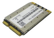
| 1x1 GTM671WFSd | GW5400 (Ventana) | OpenWrt (14.08 BSP) | NA | NA | 50 | 65 | NA | NA |
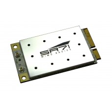
| 2x2 SR71-15 | GW5400 (Ventana) | OpenWrt (14.08 BSP) | NA | NA | 92 | 112 | NA | NA |
| 2x2 WLM200N5-26 | GW5400 (Ventana) | OpenWrt (14.08 BSP) | NA | NA | 88 | 106 | NA | NA |
| 2x2 SR71e | GW5400 (Ventana) | OpenWrt (14.08 BSP) | NA | NA | 1902 | 2452 | NA | NA |
| 3x3 HNMA-H5 | GW5400 (Ventana) | OpenWrt (14.08 BSP) | NA | NA | 111 | 119 | NA | NA |
| 3x3 WLE300NX | GW5400 (Ventana) | OpenWrt (14.08 BSP) | NA | NA | 240 | 3671 | NA | NA |
| 3x3 WLE350N5-25 | GW5400 (Ventana) | OpenWrt (14.08 BSP) | NA | NA | 2431 | 355 | NA | NA |
1. Best performing in this category (802.11n)
2. Best performing in this sub-category (802.11n, number of chains, form-factor)
3. Infrastructure tested by generating packets on PC-A and sourcing them on the STA. See the wireless testing section for more details
4. AdHoc testing is based on NODE to NODE
Tips for Improving AP Performance
- Wifi technology is constantly improving. Newer hardware will typically offer more features, better reliability/compatibility, and outperform older devices. For best results we recommend using the latest and greatest hardware.
- One of the most effective ways to improve Wifi performance is to have correctly situated in relation to the devices that will access it. If you place the AP in a location with lots of interference performance will greatly suffer.
- Test different channels. Many Wifi devices will operate on the same channel by default. Overlap could significantly reduce performance. Try different channels to avoid interferance from other AP's in the vicinity.
- Use the latest firmware. You will find the best performance and security using the latest firmware.
- Use the appropriate antenna or attenuator considering the range you plan on operating your stations from. Using a larger antenna is preferable if your AP and station are separated by some obstruction.
Where should I position my AP
- Try different locations for your AP. Guess and check method isn't the most scientific but is often the most effective method.
- Consider the most central location from all stations. Clients too far away will have poor bandwidth.
- Avoid obstruction whenever possible. Consider a ceiling mount for your AP.
- Avoid reflective surfaces, metal and steel.
- Locate the AP away from other devices emitting RF or other EM radiation. Electric motors, florescent lights, microwave ovens.
- Adjust your antenna after choosing the most suitable location.
Which Wi-Fi Channel is Best
2.4GHz
1,6,and 11 do not overlap.
5GHz
In the US: 36, 40, 44, 48, 149, 153, 157 and 161.
Note: Usable non-overlapping channels exist between 48 and 149. 52, 56, 60, 64, 100, 104, 108, 112, 116, 132, and 136 to be specific. These channels are regulated and will not work if other devices are already transmitting in this range
WiFi Terminology and Concepts
TCP Congestion Control
Starting in Linux 2.6.7 (and back-ported to 2.4.27), Linux includes alternative congestion control algorithms beside the traditional 'reno' algorithm. 2.6.13 added support for plug-able congestion control algorithms set using sysctl variable net.ipv4.tcp_congestion_control which is set to bic/cubic or reno by default depending on kernel versions.
The Internet has predominantly used loss-based congestion control (largely Reno or CUBIC) since the 1980s, relying on packet loss as the signal to slow down. While this worked well for many years, loss-based congestion control is unfortunately out-dated in today's networks. On today's Internet, loss-based congestion control causes the infamous bufferbloat problem, often causing seconds of needless queuing delay, since it fills the bloated buffers in many last-mile links. On today's high-speed long-haul links using commodity switches with shallow buffers, loss-based congestion control has abysmal throughput because it over-reacts to losses caused by transient traffic bursts.
TCP congestion control algorithms can be configured in the Kenrel under 'Networking support (NET) -> Networking options -> TCP/IP networking (INET) -> TCP: advanced congestion control (TCP_CONG_ADVANCED). The default is typically CONFIG_TCP_CONG_CUBIC which builds in CUBIC (default) and Reno. A more modern algorithm called BBR was introduced more recently.
You can select between multiple TCP congestion control algorithms via userspace sysctl:
cat /proc/sys/net/ipv4/tcp_available_congestion_control # see available algos
sysctl net.ipv4.tcp_congestion_control=reno # select Reno
References:
- https://fasterdata.es.net/host-tuning/linux/expert/
- https://linuxgazette.net/135/pfeiffer.html
- https://www.cs.helsinki.fi/research/iwtcp/papers/linuxtcp.pdf
TCP Small Queues (TSQ)
TCP Small Queues (TSQ) performs local flow control, limiting the amount of data in the queues on the sending host. Like TSO autosizing, TSQ has its own balancing act, keeping the queues small to reduce latency and head-of-line blocking (HoLB), while keeping the queues just large enough to ensure the queues on the sending host.
The kernel TSQ logic allows up to 1ms of bytes to be queued into qdisc and driver queues. However, Wifi aggregation (multiple streams) needs a bigger budget to allow bigger rates to be discovered by various TCP Congestion Control algos.
A patch has made it into the 4.15 kernel that allows wifi drivers to adjust this value as needed but drivers need to be updated to add this functionality.
Gateworks has a patch in the Newport kernel that allows userspace to change the default 1ms buffering time manually with sysctl. Increasing the buffering to something between 1ms and 9ms shows significant throughput increases for MIMO cards. For example:
sysctl net.ipv4.tcp_tsq_limit_output_interval=5 # use 5ms of buffering in TSQ logic
References:
- Ubuntu bug with discussion
- Patch allowing userspace configuration of TSQ buffer time via sysctl
- patch Linux 4.15 patch to allow wifi drivers to adjust the TSQ buffer size
- patch in LEDE adjusting TSQ logic
mac80211
mac80211 refers to the Linux kernel 802.11 MAC layer software stack written for !SoftMAC radios. For many years all radio drivers utilize this layer and those drivers are referred to as 'mac80211 drivers'. An exception to this would be the popular 'madwifi' driver used for Atheros AR5XXX based 802.11abg radios (the mac80211 driver alternative to madwifi is the ath5k driver).
References:
Regulatory Domain
Different regulatory domain's exist around the world that are regulated by various bodies - examples include the FCC for North Ameriaca, and ETSI for many European countries. Modern Linux mac80211 based drivers use the crda (Central Regulatory Domain Agent) userspace agent for regulatory domain rule database and checking. It is comprised of a database of regulatory domain rules.
Alternatively mac80211 can be configured at compile-time with CONFIG_CFG80211_INTERNAL_REGDB to use an internal regdb based on net/wireless/db.txt which can be easier to udpate if need be for your application (providing you are making changes that are legal in the regulatory domain you will be operating in). One example of where this would be useful is if you are licensed to operate in the US Public Safety band, which crda has no support for.
Notes:
- OpenWrt uses this option
- If you enable CONFIG_CFG80211_INTERNAL_REGDB and fail to overwrite the default net/wireless/db.txt a default domain will be used which sets the 'no IR' flag on all channels (meaning you can not transmit)
The iw list command will print out frequencies that are supported or may be blocked due to current domain, see example below showing the no IR statement:
Frequencies:
		* 5955 MHz [1] (20.0 dBm) (no IR)
Current regulatory domain can be seen with the command and set to US with example below:
root@jammy-venice:~# iw reg get
global
country 00: DFS-UNSET
	(755 - 928 @ 2), (N/A, 20), (N/A), PASSIVE-SCAN
	(2402 - 2472 @ 40), (N/A, 20), (N/A)
	(2457 - 2482 @ 20), (N/A, 20), (N/A), AUTO-BW, PASSIVE-SCAN
	(2474 - 2494 @ 20), (N/A, 20), (N/A), NO-OFDM, PASSIVE-SCAN
	(5170 - 5250 @ 80), (N/A, 20), (N/A), AUTO-BW, PASSIVE-SCAN
	(5250 - 5330 @ 80), (N/A, 20), (0 ms), DFS, AUTO-BW, PASSIVE-SCAN
	(5490 - 5730 @ 160), (N/A, 20), (0 ms), DFS, PASSIVE-SCAN
	(5735 - 5835 @ 80), (N/A, 20), (N/A), PASSIVE-SCAN
	(57240 - 63720 @ 2160), (N/A, 0), (N/A)

phy#0 (self-managed)
country 00: DFS-UNSET
	(2402 - 2472 @ 40), (N/A, 20), (N/A)
	(2457 - 2482 @ 20), (N/A, 20), (N/A), PASSIVE-SCAN
	(5170 - 5330 @ 160), (N/A, 20), (N/A), AUTO-BW, PASSIVE-SCAN
	(5490 - 5730 @ 160), (N/A, 20), (N/A), AUTO-BW, PASSIVE-SCAN
	(5735 - 5895 @ 160), (N/A, 20), (N/A), AUTO-BW, PASSIVE-SCAN
	(5945 - 7125 @ 160), (N/A, 20), (N/A), AUTO-BW, PASSIVE-SCAN

root@jammy-venice:~# iw reg set US
root@jammy-venice:~# iw reg get
global
country US: DFS-FCC
	(902 - 904 @ 2), (N/A, 30), (N/A)
	(904 - 920 @ 16), (N/A, 30), (N/A)
	(920 - 928 @ 8), (N/A, 30), (N/A)
	(2400 - 2472 @ 40), (N/A, 30), (N/A)
	(5150 - 5250 @ 80), (N/A, 23), (N/A), AUTO-BW
	(5250 - 5350 @ 80), (N/A, 24), (0 ms), DFS, AUTO-BW
	(5470 - 5730 @ 160), (N/A, 24), (0 ms), DFS
	(5730 - 5850 @ 80), (N/A, 30), (N/A), AUTO-BW
	(5850 - 5895 @ 40), (N/A, 27), (N/A), NO-OUTDOOR, AUTO-BW, PASSIVE-SCAN
	(5925 - 7125 @ 320), (N/A, 12), (N/A), NO-OUTDOOR, PASSIVE-SCAN
	(57240 - 71000 @ 2160), (N/A, 40), (N/A)

phy#0 (self-managed)
country 00: DFS-UNSET
	(2402 - 2472 @ 40), (N/A, 20), (N/A)
	(2457 - 2482 @ 20), (N/A, 20), (N/A), PASSIVE-SCAN
	(5170 - 5330 @ 160), (N/A, 20), (N/A), AUTO-BW, PASSIVE-SCAN
	(5490 - 5730 @ 160), (N/A, 20), (N/A), AUTO-BW, PASSIVE-SCAN
	(5735 - 5895 @ 160), (N/A, 20), (N/A), AUTO-BW, PASSIVE-SCAN
	(5945 - 7125 @ 160), (N/A, 20), (N/A), AUTO-BW, PASSIVE-SCAN

root@jammy-venice:~#
References:
- http://wireless.kernel.org/en/developers/Regulatory
- http://git.kernel.org/cgit/linux/kernel/git/linville/wireless-regdb.git/
Automatic Channel Selection (ACS)
The Automatic Channel Selection (ACS) feature is useful if you want the operating channel to be selected based on usage in your area. A specification exists on how this is done.
Notes:
- a modern hostapd (2013-11-21) must be used and built with CONFIG_ACS
- specify channel=0 or channel=acs_survey in hostapd.conf
References:
Dynamic Frequency Selection (DFS)
Dynamic Frequency Selection (DFS) is a specification required by certain regulatory domains on specific channels in order to eliminate conflicts with weather and government/military radar equipment. For this reason it is sometimes know as 'radar detection' (which is likely a better description of it). This is often required for channels on the 5.8GHz band and there are specific rules for how and if a radio can transmit on these channels.
Because DFS is complex many small office and home office AP's as well as some enterprise AP's don't allow operation at all on DFS channels in the 5GHz band and many client devices are not certified for DFS operation.
Notes:
- a modern hostapd (2013-11-21) must be used
- not supporting DFS limits the channels that can be used:
- In the US (FCC regulatory domain) there are 4 channels in the 5.8GHz band that do not require DFS and 4 that do
The ath9k as well as ath10k (and possibly others) fully support ETSI DFS and FCC DFS requirements according to reports on the linux-wireless maillist and various radio certifications.
References:
Antenna Selection
MIMO (Multiple-In Multiple-Out) radios (802.11n and 802.11ac) have multiple transmit and multiple receive antennas (also known as 'chains'). On some devices/drivers you can configure which are used for tx as well as rx using the 'set antenna' command:
iw phy0 info | grep Antenna # show available Antennas
iw phy0 set antenna 1 2 # set tx for antenna1, rx for antenna 2
iw phy0 set antenna 1 3 # set tx for antenna1, rx for antenna 2 and 3
- the values are a bitmask (ie 1 for antenna1, 2 for antenna2, 4 for antenna 3, 3 for antenna 1&2, 6 for antenna 2&3 etc)
- typically the interface needs to be in a down state (ifconfig wlan0 down) in order to set the antenna selection bitmasks
- not all drivers support this
Guard band Interval (GI)
The guard band interval describes how long you wait in between packets before transmission. For 802.11 OFDM this is 800ns hjwever 802.11n (also supported in 802.11ac) introduced a 400ns option to increase data-rates. This new 400ns GI is referred to as a 'short' GI and the original 800ns is referred to as a 'long' GI.
Notes:
- The rate control algorithm may decide between short GI and long GI based on statistics and alternate this over time
Channel Width
Channel Width refers to the bandwidth per channel and varies per 802.11 mode:
- 802.11b - defines 20MHz channel width (this allows for 3 non-overlapping channels out of the 11 channels defined in the 2.4GHz band)
- 802.11n - added the capability of 40MHz channels referred to as 'HT' or High Throughput channels. When using 40MHz HT channels you must specify HT40- to use the current channel specified frequency and the 20MHz below it, and HT40+ to use the current channel specified frequency and the 20MHz above it
- 802.11ac - added the capability of 80MHz and 160MHz channels referred to as 'VHT' or Very High Throughput channels
- Wave 2 - added an 80+80MHz configuration that could be set for two non contiguous bands to minimize interference
Some drivers also support 'half' channel bandwidth (10MHz) and/or 'quarter' channel bandwidth (5Mhz) which is useful if you don't need the bandwidth provided by standard (20MHz) channels or HT/VHT channels and instead want more channel separation.
Note that as you increase the channel width, you increase channel overlap and decrease separation.
Modulation Rates
Various 802.11 specifications allow for varying modulation schemes which trade off error resilience, throughput, and effective distance. Each transmission can vary the modulation scheme and A 'rate control algorithm' has the ability to change this dynamically for each node being transmitted to based on different statistics.
Modulation Schemes:
- 802.11b - allowed for 1M, 2M, 5.5M, 11M CCK modulation rates
- 802.11g - added additional OFDM modulation schemes to allow for 6M, 9M, 12M, 18M, 24M, 36M, 48M, and 54M modulation rates
- 802.11n - added additional modulation schemes to allow several more rates and introduced the concept of a Modulation and Coding Scheme (MCS) index to describe them
- 802.11ac - added 2 additional MCS indexes for new 256-QAM modulation schemes
- Wave 2 - Improved on the original Wave 1 release by adding MU-MIMO and an optional 4th spatial stream, see this Cisco FAQ for more information
- 802.11ax - added 2 additional MCS indexes for new 1024-QAM modulation schemes, support for additional frequency bands, and OFDMA.
Notes:
- you can use the 'iw dev wlan0 set bitrates' command to set bitmasks to indicate which modulation rates to allow
- there is not a standard mac80211 way to determine what modulation rate is being used, or what the rate control algorithm is doing
- some devices/drivers use the mac80211 rate control algorithms (there are 2 to choose from at compile time) and others use algorithms baked into device firmware
- Modulation Table Online
Adhoc mode (IBSS)
Though not part of the 802.11 spec (was part of the 802.11 draft), a popular mode is referred to as 'adhoc' mode or 'IBSS' mode. In this mode there is no authentication/de-authentication and no concept of an Access Point. Instead a 'network' is defined by the 'BSSID' used by the nodes. Network discovery is performed by listening to beacons and beacon transmission is shared by nodes in a BSSID (each node has a beacon timer with a random backoff interval which is reset when a beacon matching the nodes network is received which tends to share the beacon transmission load). A scheme was defined so that nodes would join a network if a beacon is received matching the nodes network configuration and BSSID's would 'merge' depending on timestamps however this is not implemented consistently and can cause issues such as merge storms across various drivers/chipsets. Because of this often adhoc networks will define a BSSID instead.
Because adhoc mode is not in the 802.11 spec and is not as popular as infrastructure mode (AP/STA) it isn't always as stable as infrastructure mode.
While not required, Adhoc networking is often used as the underlying connection mode for layer2 (MAC layer) and layer3 (IP layer) MESH networks such as olsrd.
Check that IBSS is available to use:
iw phy0 info
When using adhoc mode, you do not need hostapd or wpa_supplicant and the iw tool can be used to join/leave adhoc network:
iw dev wlan0 set type ibss # change an existing wlan0 device to ibss mode (if must be down)
iw dev wlan0 ibss join myssid 5180 # join the 'myssid' network, on 5180MHz (20MHz) and rely on IBSS discovery and merging
iw dev wlan0 ibss leave # leave the adhoc network
Some other useful commands for adhoc nodes:
iw phy phy0 interface add wlan1 type ibss # create an interface on phy0 called wlan1 configured for adhoc mode
iw dev wlan0 ibss join myssid 5180 0a:0b:0c:0d:0e:0f # join the 'myssid' network, on 5180MHz (20MHz) with fixed bssid
iw dev wlan0 ibss join myssid 5180 HT40- 0a:0b:0c:0d:0e:0f # join the 'myssid' network, on 5180MHz (40MHz using 5180 and the ch below) with fixed bssid
Creating an interface that already exists will cause an error:
root@OpenWrt:/# ls /sys/class/net/
bond0            can0             gretap0          lo
bonding_masters  eth0             ifb0             usb0
br-lan           gre0             ifb1             wlan0
root@OpenWrt:/# iw phy phy0 interface add wlan0 type ibss
command failed: Too many open files in system (-23)
root@OpenWrt:/#
Frame Aggregation
As data rates increase the overhead of management and headers starts to create bandwidth bottlenecks. The 802.11n specification introduced the concept of Frame Aggregation to combat this. Two types of aggregation was introduced: A-MPDU and A-MSDU.
This does not need to be enabled and should be used automatically by the driver if the card has the capability.
References:
Quality of Service
The 802.11e specification added various aspects to 802.11 to create the concept of multiple data queues with different priorities in order to create a quality of service.
References:
- http://en.m.wikipedia.org/wiki/802.11e#Enhanced_distributed_channel_access_.28EDCA.29
- https://wireless.wiki.kernel.org/en/developers/documentation/mac80211/queues
Doodle Labs WiFi Radios (Details)
Part Numbering Scheme
The following terminology used by Doodlelabs is required:
Grade Breakdown:
- Military Grade - This is their Industrial grade option. This grade has extended temp of -40C - +85C. This grade also has antenna port protection, and is built to a higher standard than their other radio's.
- Enterprise - This is their Indoor Commercial grade option. This grade has a temperature range of 0C - +60C and has no antenna port protection.
- Outdoors - This is their Outdoor Commercial grade option. This grade has a temperature range of -40C - +40C and has antenna port protection.
The model number NM-770-2F is broken down into three sections: NM, 770, 2F
- NM - The 'N' refers to this being an 80211N radio. If this were 'ACM', for example, that would mean the radio is a 80211AC radio. The last character of the first section refers to the grade the radio is. In this case, the 'M' stands for Military, or rugged, grade.
- 770 - This number refers to the middle frequency of the frequency range that the card supports. In this case, the card supports 746~798, the midpoint center frequency resulting in 770. If there is no number, and instead has either 'DB' or 'TB', that only means "Dual-Band" and "Tri-Band", respectively. When DB is specified, that refers to both the 2.4GHz and 5.8GHz range. TB refers to DB, but also includes the 4.9GHz frequency range.
- 2F - The number '2' refers to the number of chains the radio has. In this case, there are two chains on this radio. A '3' would indicate three chains. The 'F' alludes to the fact that each chain get's frequency shifted through the frequency shifting module. This means that you're always going to have a FES module per chain.
So in conclusion, the NM-770-2F system includes a 80211N radio with two chains, each getting frequency shifted by a FES module to the 770MHz range.
Licensed vs Unlicensed
In the US, the difference between Licensed and Unlicensed comes down to how the FCC regulates the frequency spectrum. In general, Doodlelabs refers to 'unlicensed' radio's the 2.4GHz and 5GHz range frequencies. All other frequencies fall under being 'licensed'.
Frequency Shifting/Power Level Mappings
Coming Soon.
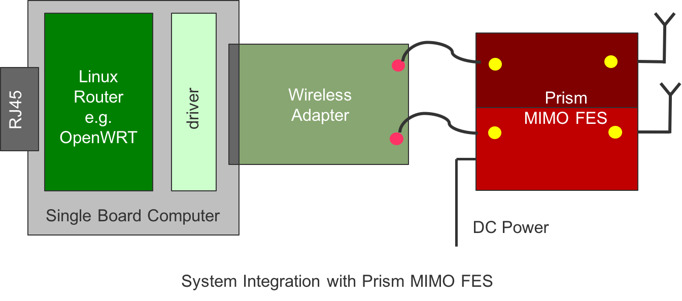
Doodlelabs Prism-FES (Front End Subsystems)
Doodlelabs creates frequency shifting modules to allow frequencies between 700MHz - 6.5GHz, while using standard linux drivers. These systems are comprised of one ath9k/ath10k radio with a FES module on each chain. The below picture will help visualize this:

In this system, a radio has two separate FES modules per chain. From the factory, Doodlelabs calibrates each chain on a specific radio to a particular FES module. This means that a radio with 2 chains is specifically paired with two FES modules. You can find which FES modules are paired with what radio by comparing serial numbers (Hint: all components in the system have the same serial). It's very highly recommended by Doodlelabs that nothing is mixed and matched.
Radio's configured to be used in a Prism-FES all have EEPROM values programmed in to only allow a maximum of 10dBm output (per chain). Anything higher will damage the frequency translator. For this reason, Prism-FES's that are using ath10k are recommended to stay away from using the STA firmware (999.999.0.636) as we found that this firmware does not honor the EEPROM settings and configures the radio to output much higher than 10dBm.
FES Power Discussion
For example, the GW6100 can support approximately 8W of power to the Mini-PCIe slot (at 3.3V).
The Doodle Labs radio requires around 2W for the radio portion which should work fine in the Mini-PCIe site.
For the FES amplifier you will need and additional 16W of power which would be over the limit of what we can provide from the slot.
Doodle Labs does however have an optional DC/DC converter (6-38V input) which can be used to power the FES directly from your VIN supply. See the following link for picture of the DC/DC: https://doodlelabs.com/products/industrial-wifi-transceivers/datasheet-nm-5500-2f/
By using the optional DC/DC you can also mount the FES away from the board to optimize your thermal solution. The FES is pretty small and generates a lot of heat so I would suggest mounting it directly to your enclosure for maximum heat transfer and then you can cable from the radio to the FES.
If the Doodle Labs DC/DC doesn't fit your design needs there are lots of other vendors that make DC/DC modules that you could use for the FES power. As an example see the following link: https://www.cui.com/product/resource/pyb20-u.pdf
References
- http://www.doodlelabs.com/products/prism-fes/
- http://www.doodlelabs.com/products/mimo-radio-transceivers/
Validated USB radios from Amazon
Sometimes a USB WIFI device is the only option available. Gateworks seldom validates these radios, from our limited testing "AmazonBasics Wi-Fi 11N USB Adapter - 300 Mbps, Black" is an excellent inexpensive choice. This radio's drivers are already built in the kernel providing a turn key wireless interface.
https://www.amazon.com/AmazonBasics-Wi-Fi-11N-USB-Adapter/dp/B071Y6Y83W/
Attachments (6)
- GW17001-228x228.jpg (7.7 KB ) - added by 8 years ago.
- Prism-FES-1.png (75.3 KB ) - added by 8 years ago.
-
GW17032.png
(28.1 KB
) - added by 7 years ago.
GW17032 WLE900VX Radio
-
ax200u.png
(142.0 KB
) - added by 5 years ago.
ax200U
- pceax-ap-antennas.png (148.0 KB ) - added by 14 months ago.
- gw17052antenna.png (68.7 KB ) - added by 3 days ago.
Download all attachments as: .zip